Steering column assembly

a technology for steering columns and assemblies, applied in steering parts, vehicle components, transportation and packaging, etc., can solve the problems of affecting the operation of the steering column,

Active Publication Date: 2015-05-19
TRW STEERING SYST POLAND Z O O +1
View PDF14 Cites 51 Cited by
  • Summary
  • Abstract
  • Description
  • Claims
  • Application Information

AI Technical Summary

Benefits of technology

[0008]The applicant has found that, in some cases, a severe and rapid rotation of the fixed cam portion on releasing the clamp can occur as the strain force stored in the assembly, perhaps in the spring, or outer tube or even the clamp pin, is released. This can cause the fixed cam portion to rotate around the axis of the clamp pin and to knock against a part of the clamp bracket causing an undesirable audible clicking noise. This can occur, for example, where the support bracket has an arm with an outer leaf and an inner leaf with the cam portion passing through the outer leaf with a clearance fit so that it only acts upon the inner leaf. The cam when it rotates may strike the side of the opening in the outer leaf which can cause a loud click noise or even damage the outer leaf. The assembly of the present invention ameliorates and in some cases may completely eliminate this problem.
[0021]Where the arm of the bracket comprises and inner leaf and an outer leaf, with the fixed cam passing through an opening in the outer leaf to engage the inner leaf a liner of soft material, such as plastic, may be provided within the slot in the outer leaf of the arm of the support bracket, to further reduce any noise due to movement, such as may occur towards the end of the release of the clamp assembly, if rotation of the fixed cam portion occurs towards the end of the release of the cam assembly. At this point, much of the strain energy will have been dissipated, so the rotation will be relatively slow and the liner will absorb the energy.

Problems solved by technology

The applicant has found that, in some cases, a severe and rapid rotation of the fixed cam portion on releasing the clamp can occur as the strain force stored in the assembly, perhaps in the spring, or outer tube or even the clamp pin, is released.
This can cause the fixed cam portion to rotate around the axis of the clamp pin and to knock against a part of the clamp bracket causing an undesirable audible clicking noise.
The cam when it rotates may strike the side of the opening in the outer leaf which can cause a loud click noise or even damage the outer leaf.
The skilled person will understand that this means that the length of the cam changes a relatively large amount for a given rotation of the moving cam, and requires relatively steep ramp angles on the cam lift faces.

Method used


Image

  • Steering column assembly
  • Steering column assembly
  • Steering column assembly

Examples


Embodiment Construction

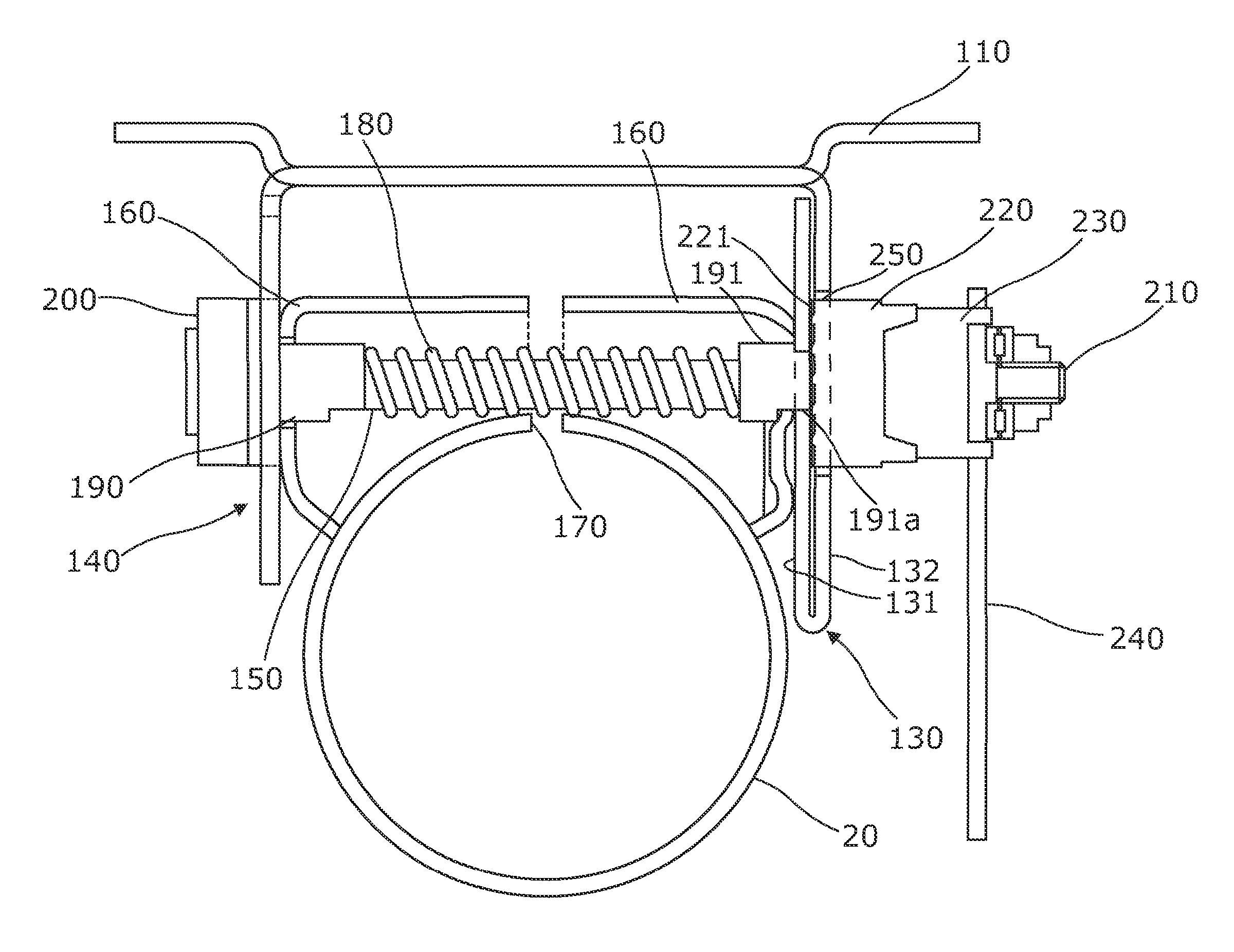
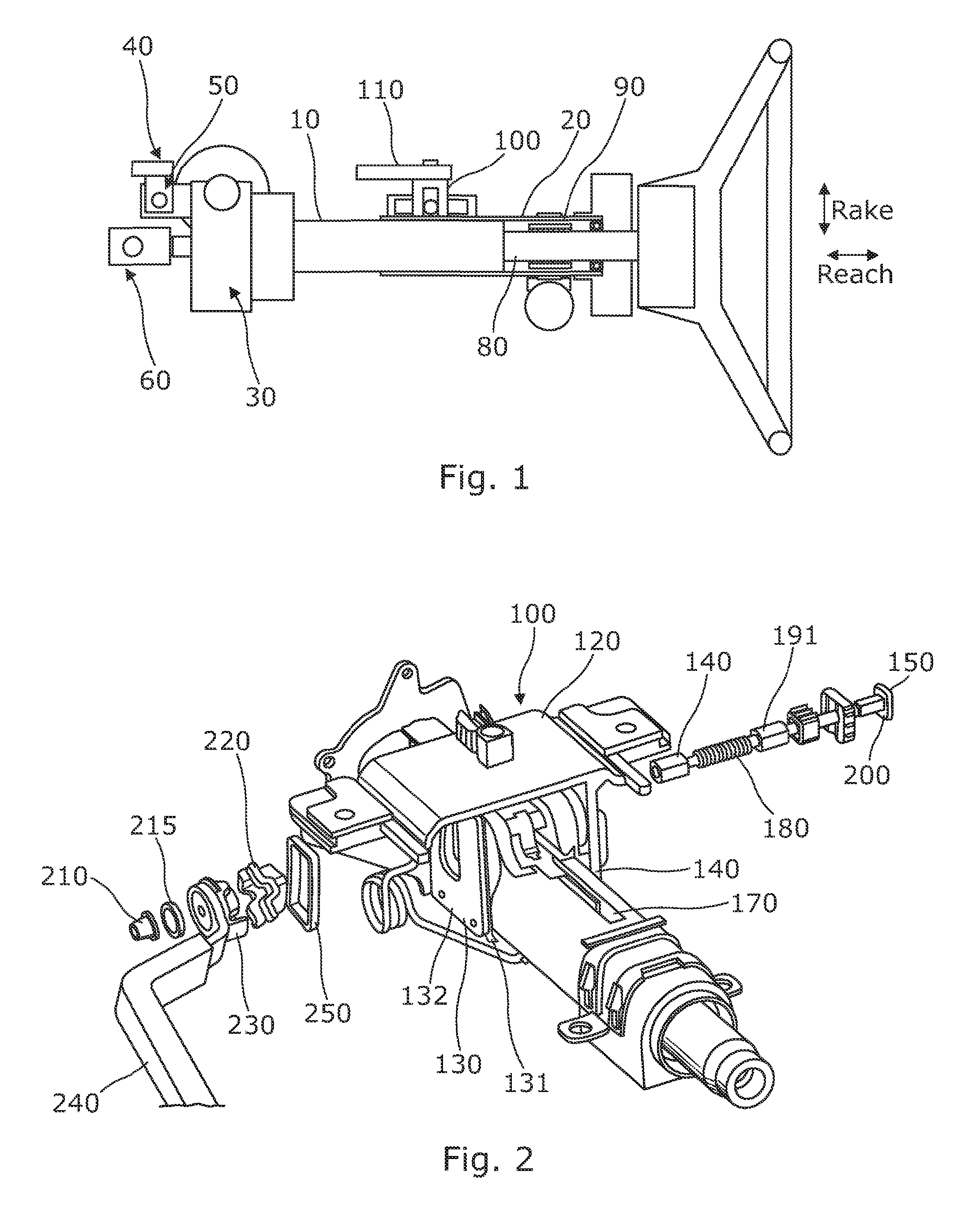
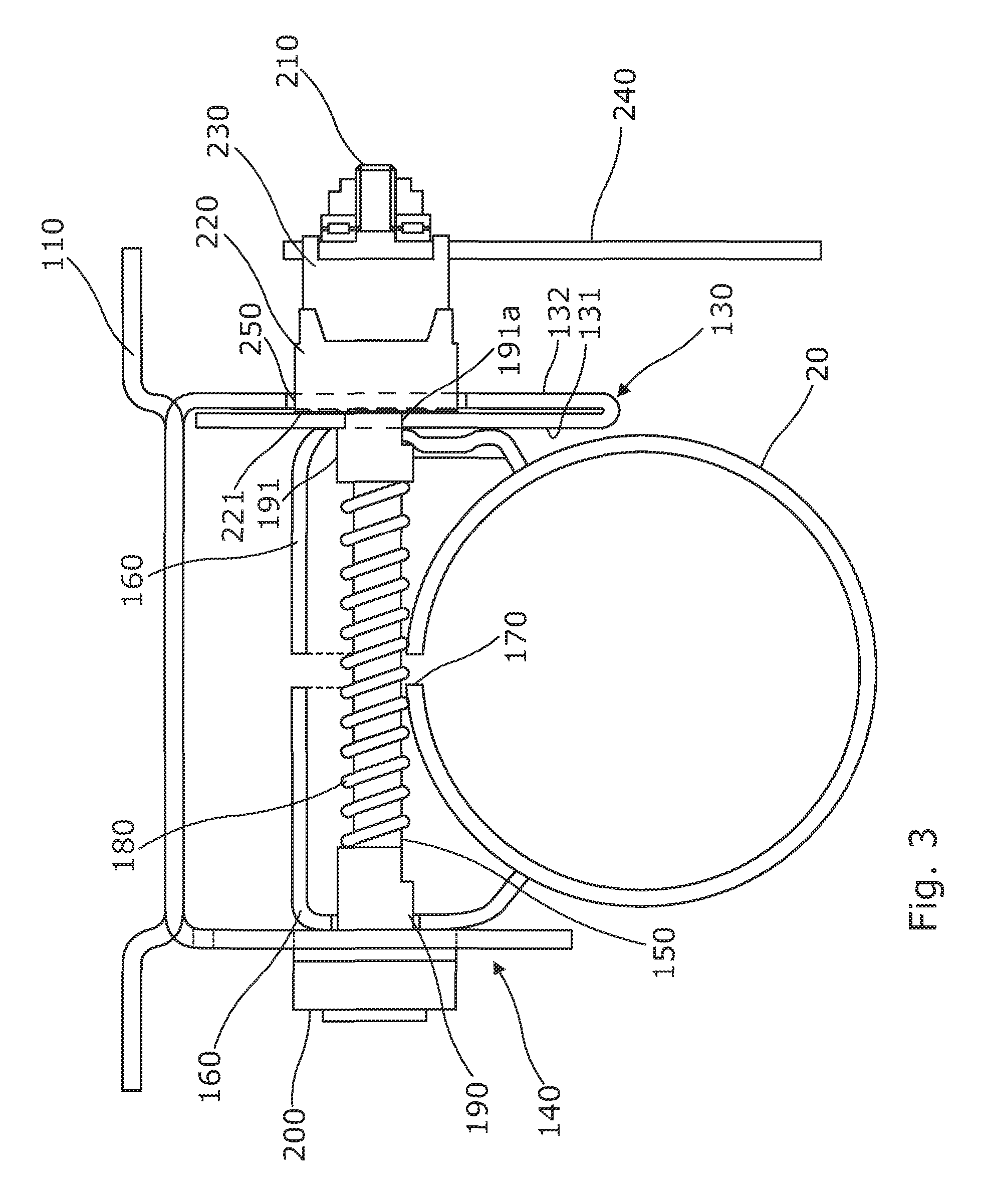
[0039]As shown in FIG. 1, a steering column assembly comprises a sleeve or shroud that comprises an inner member 10 and an outer member 20 which receives a portion of the inner member 10. The inner and outer members 10, 20 are of metal and tubular cylindrical with the inside diameter of the outer member 20 being only slightly greater than the outside diameter of the inner member 10 so as to permit relative movement between them by sliding. In the example, the inner member is secured to an electric power steering actuator 30 which is secured to the vehicle body 40 at a pivot point 50 and in turn connects to a rack and pinion through an intermediate coupling 60. The outer member 20 extends away from that towards a steering wheel 70 as is known in the art. The steering wheel 70 is supported by a telescopic steering shaft (shown as 80 in FIG. 1) that is free to rotate within the steering column shroud 20, 10. It is located within the shroud by bearing 90. In other arrangements the outer...


PUM


Abstract

A steering column assembly comprises a steering column shroud comprising an inner and an outer tubular member, a support bracket which is fixed to part of the vehicle, and a clamp assembly which includes a cab mechanism having a fixed portion and a moving portion and a clamp pin which passes through arms of the support bracket, the clamp pin being provided with a first reaction member located towards one end of the pin outside of one arm of the support bracket and a second reaction member located towards the other end of the clamp pin outside of the other arm of the support bracket such that the arms of the bracket are located on the clamp pin between the reaction members and with the cam assembly located between the outside of one arm and one of the reaction members. The fixed cam portion is mechanically connected to the support bracket such that at least during an initial release phase of the clamp assembly the force required to produce a rotational movement of the fixed cam portion relative to the support bracket exceeds any rotational force exerted on the fixed part due to strain energy stored in the assembly.

Description

CROSS-REFERENCE TO RELATED APPLICATIONS[0001]This application is a national stage of International Application No. PCT / GB2011 / 051927 filed Oct. 7, 2011, the disclosures of which are incorporated herein by reference in entirety, and which claimed priority to European Patent Application No. EP 10187054.1 filed Oct. 8, 2010, the disclosures of which are incorporated herein by reference in entirety.BACKGROUND OF THE INVENTION[0002]This invention relates to improvements in steering column assemblies.[0003]Steering column assemblies for automotive vehicles and the like are increasingly required to be adjustable for rake and, in many cases, reach. This requires the column shroud, within which the steering column is rotatably located, to be fixed to the vehicle by a clamp mechanism which can be locked and unlocked to either prevent movement or permit adjustment of the column shroud position respectively.[0004]One common arrangement uses a column shroud which comprises an inner tubular membe...

Claims


Application Information

Patent Timeline
Patent Type & Authority Patents(United States)
IPC IPC(8): B62D1/184B62D1/18B62D1/187
CPCB62D1/18B62D1/184B62D1/187
Inventor DAVIES, NICLASMUTHUKALYANI, SATHISH BABUKWASNY, SLAWOMIR
Owner TRW STEERING SYST POLAND Z O O
Why Eureka
Try Eureka