Connector of a light-emitting-diode lamp tube

a technology of light-emitting diodes and lamp tubes, which is applied in the direction of semiconductor devices for light sources, coupling device connections, lighting and heating apparatus, etc., can solve the problems of mercury pollution, fluorescent lamps can be fragile, and the person or woman may be poisoned

Inactive Publication Date: 2015-05-19
JUSTING TECH
View PDF30 Cites 4 Cited by
  • Summary
  • Abstract
  • Description
  • Claims
  • Application Information

AI Technical Summary

Benefits of technology

[0011]Accordingly, the primary object of the present invention is to provide a connector by which a user can utilize a simple insertion operation to form electric conduction by contact, so that the connector is able to be applied to a fluorescent lamp tube, a power-saving lamp tube or a similar lamp tube.
[0013]The connection terminal is provided at least with two elastic terminal units which are inserted directly into the connector through a conductive terminal of each end cap, and form electric conduction by contact with each elastic terminal unit to transmit electricity, thereby constituting a structure that can be assembled easily, and parts thereof can be replaced and repaired by an ordinary person.

Problems solved by technology

In addition, if a person touches or adsorbs the mercury by accident, then he or she may be poisoned.
On the other hand, although a conventional fluorescent lamp is cheaper, its wastes can result in mercury pollution or the fluorescent lamp can be fragile.
However, the prior art is provided with following shortcomings:1. The assembling process of the external modules is tedious and complicated; therefore, the assembling cost is higher.2. The quality of welding is difficult to be determined by naked eyes; therefore, tiny cracks may be formed.
Moreover, if the levels of welders are not consistent, the welding quality can be affected easily, thereby increasing the defective fraction.3. An ordinary LED lamp tube is still used in a conventional lamp holder.

Method used


Image

  • Connector of a light-emitting-diode lamp tube
  • Connector of a light-emitting-diode lamp tube
  • Connector of a light-emitting-diode lamp tube

Examples


Embodiment Construction

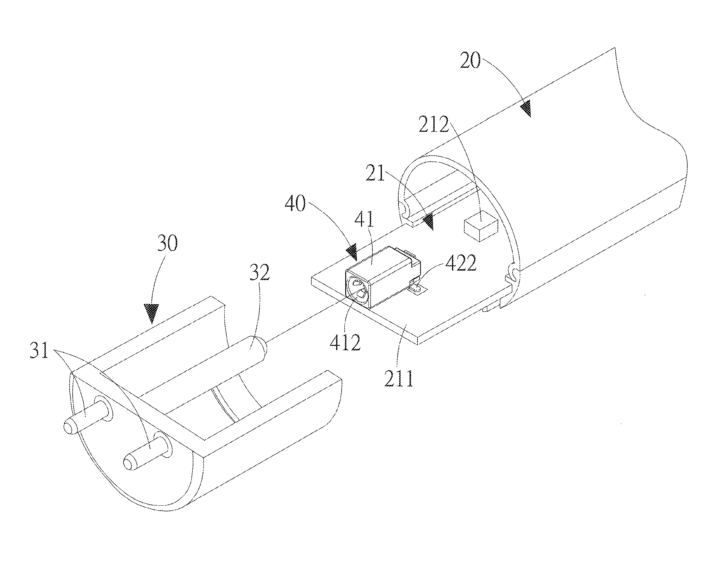
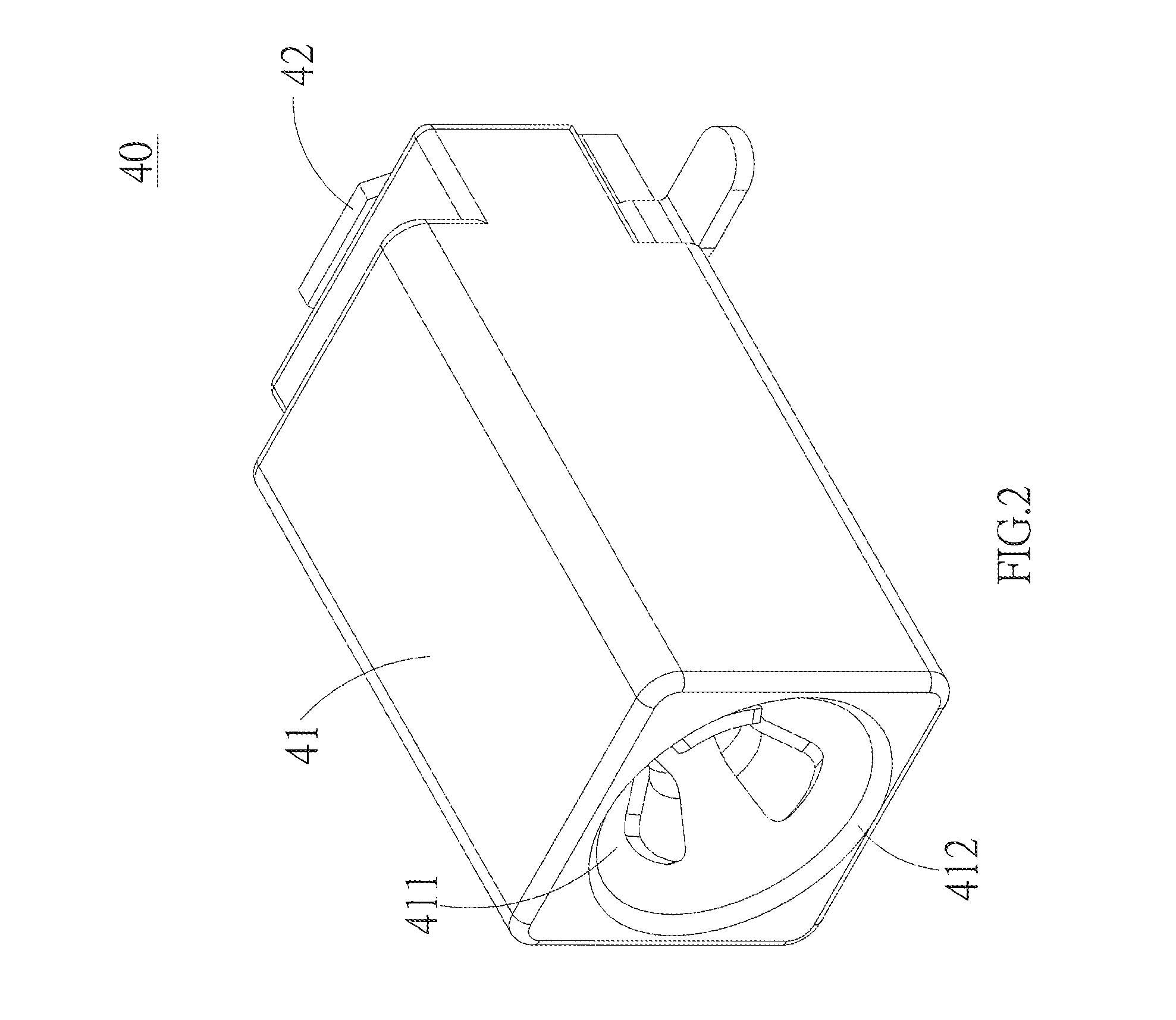
[0032]FIG. 2 discloses a three-dimensional structural view of a connector of a preferred embodiment, according to the present invention; whereas, FIG. 3 shows a cutaway structural view of the connector of the preferred embodiment, according to the present invention. The connector 40 comprises at least an insulator body 41, a conductive plate 42 and a connection terminal 43.

[0033]The insulator body 41 is provided with an insertion slot 411, and a front end of the insertion slot 411 is formed with an insertion port 412. Referring to FIG. 4 at a same time, a rear end of the insertion port 412 is formed with an open pore 413 and two sides of the insulator body 41 are formed respectively with an opening 414 which is connected with the insertion slot 411.

[0034]The conductive plate 42 is disposed on the insulator body 41 corresponding to the open pore 413, the conductive plate 42 is provided with a first conducting unit 421 at the open pore 413, and a welding unit 422 which is extended fro...


PUM


Abstract

By a simple insertion operation, a connector forms electric conduction by contact, and is therefore applied to a fluorescent lamp tube, a power-saving lamp tube or a similar lamp tube. A light-emitting-diode lamp tube of the present invention includes a light module and two end caps. The connector connects the two end caps at two ends of the light module, and is composed of an insulator body, a conductive plate and a connection terminal. The insulator body includes an insertion slot, the connection terminal is disposed in the insertion slot to connect with the conductive plate, and includes two elastic terminal units. By inserting directly a conductive terminal of the end cap into the connector, and forming electric conduction by contact with each elastic terminal unit, electricity is transmitted, thereby constituting a structure that can be assembled easily, and parts thereof can be replaced and repaired by an ordinary person.

Description

BACKGROUND OF THE INVENTION[0001]a) Field of the Invention[0002]The present invention relates to a connector of a light-emitting-diode lamp tube, and more particularly to a connector by which a user can utilize a simple insertion operation to form electric conduction by contact. Therefore, the connector is able to be applied to a fluorescent lamp tube, a power-saving lamp tube or a similar lamp tube.[0003]b) Description of the Prior Art[0004]An early fluorescent lamp tube is mostly made of glass and contains small amount of mercury. Therefore, one should be very careful when taking or installing the fluorescent lamp tube; if the fluorescent lamp tube is broken accidentally, the mercury will flow out and damage the environment. In addition, if a person touches or adsorbs the mercury by accident, then he or she may be poisoned. On the other hand, although a conventional fluorescent lamp is cheaper, its wastes can result in mercury pollution or the fluorescent lamp can be fragile.[0005...

Claims


Application Information

Patent Timeline
Patent Type & Authority Patents(United States)
IPC IPC(8): F21V33/00F21K99/00F21S4/00F21V23/06H01R12/70H01R12/72H01R13/11H01R33/08
CPCH01R13/111F21K9/175F21S4/008F21V23/06H01R12/7088H01R33/0854H01R12/724F21S4/28F21K9/272
Inventor SU, CHIA-CHINGYEN, CHIH-YUAN
Owner JUSTING TECH
Why Eureka
Try Eureka