Vertebral osteosynthesis equipment

a technology of vertebral osteosynthesis and equipment, applied in the direction of staples, nails, diagnostics, etc., can solve the problem that the vertebral osteosynthesis plate cannot be securely secured, and the disadvantage of the application of tightness is significant, so as to eliminate any insertion of screws, facilitate the application, and facilitate the effect of implantation

Active Publication Date: 2015-05-19
MEDICREA INT SA
View PDF11 Cites 31 Cited by
  • Summary
  • Abstract
  • Description
  • Claims
  • Application Information

AI Technical Summary

Benefits of technology

[0013]The lateral branches of the clip have a section allowing them to support this impaction and a width allowing them to rest against the cortical bones defining the vertebral plates in a stable manner, along these cortical bones, notwithstanding the constraints resulting from the deformation of the intermediate branch of the clip.
[0014]The clip of the equipment according to the invention is therefore particularly simple and quick to position and eliminates any insertion of screws in the vertebrae, and therefore all risk connected to possible unscrewing. Furthermore this clip presents a slight flexibility that the vertebral osteosynthesis plates do not present, that is favorable for stimulating the growth of bone cells in view of vertebrae fusing.

Problems solved by technology

Some existing vertebral osteosynthesis plates have a significant disadvantage of not allowing this tight application to be securely achieved, in such a way that the vertebral fusion may not take place or may take place imperfectly.

Method used


Image

  • Vertebral osteosynthesis equipment
  • Vertebral osteosynthesis equipment
  • Vertebral osteosynthesis equipment

Examples


Embodiment Construction

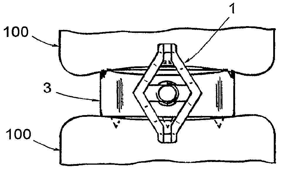
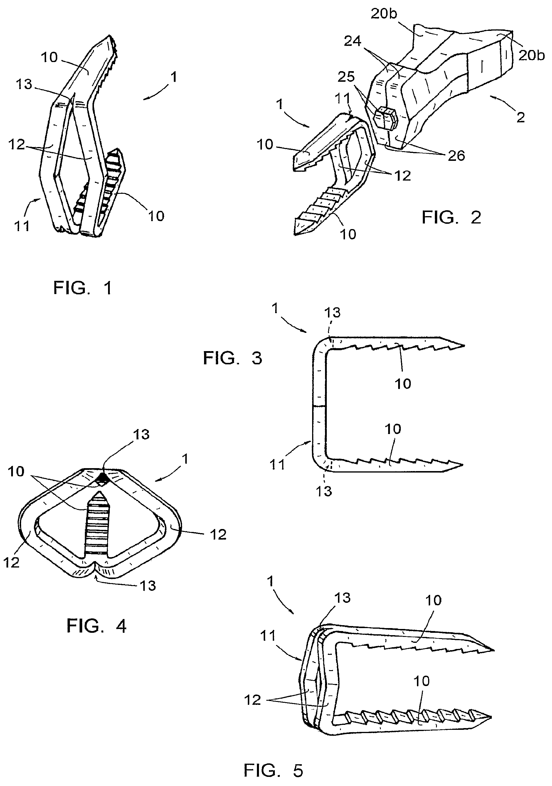
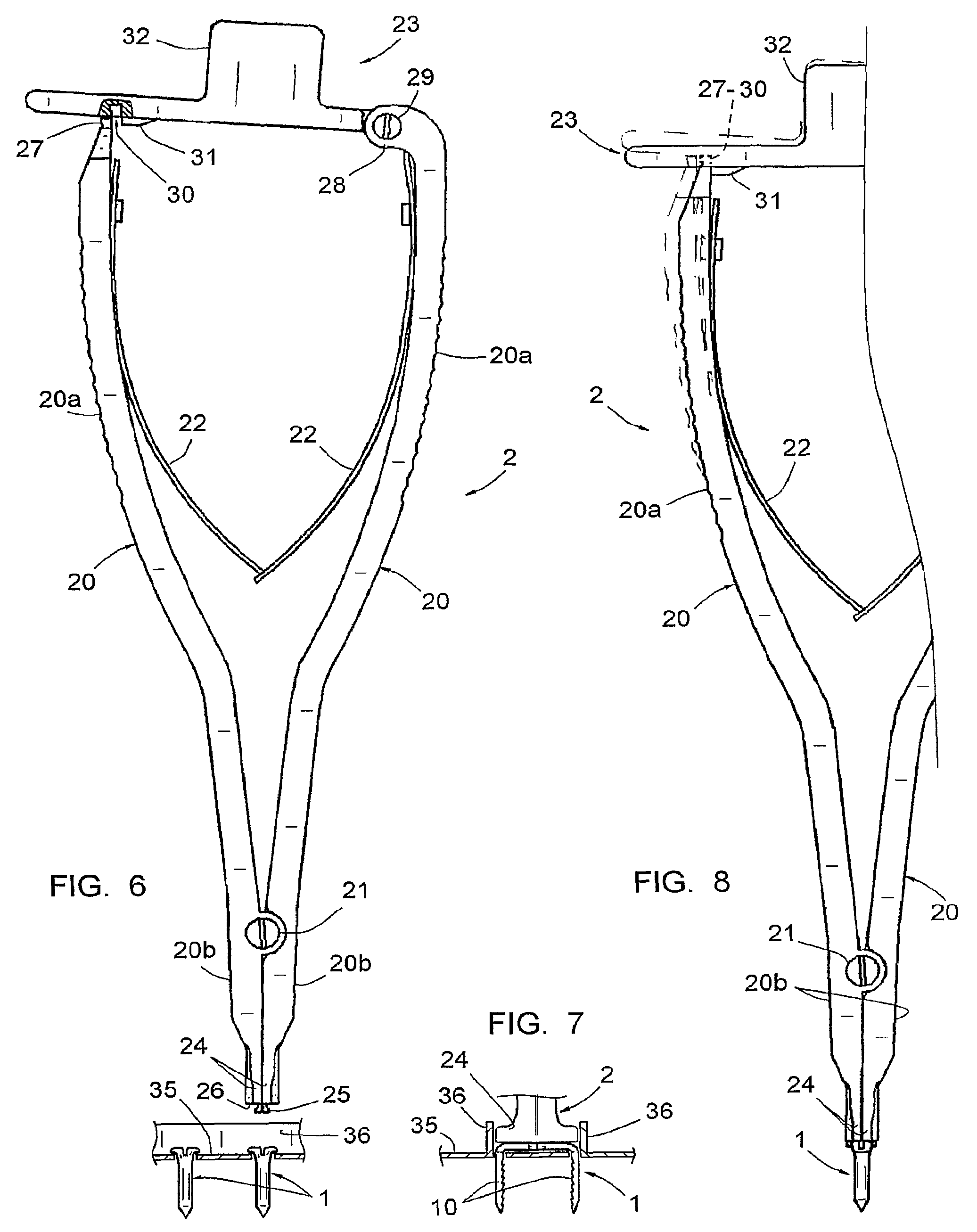
[0048]This clip 1 is part of an item of vertebral osteosynthesis equipment, which also includes other clips 1 in different sizes, an instrument 2 shown in FIGS. 6 to 9, allowing gripping, impacting and deformation of each clip 1, and at least one intervertebral implant 3, more clearly seen in FIGS. 10 to 12.

[0049]The clip 1 has a U-shaped side view and, in the example represented, is obtained by double folding a band of titanium.

[0050]Its lateral branches 10 are designed to be inserted in the vertebral bodies 100 of two vertebrae to be treated, as shown in FIGS. 10 to 12, by impaction on the intermediate branch 11 of the clip, and are designed to rest against the cortical bones defining the plates of these vertebral bodies 100, along said plates. The lateral branches 10 have sections and widths provided as a result, particularly widths of 3 mm and thicknesses of 1.5 mm.

[0051]Different clips 1 from the series of clips that comprise the equipment have lateral branches 10 with differen...


PUM


Abstract

This equipment includes at least one U-shaped clip (1) whose lateral branches (10) have sections and widths such that they may be inserted in the vertebral bodies (100) of two vertebrae by impaction on the intermediate branch (11) of the clip (1), so as to rest along the cortical bones of the vertebral bodies, and whose intermediate branch (11) is deformable in such a way as to allow a reduction of the distance between the lateral branches (10); the intermediate branch, before implantation, has a length such that one of the lateral branches (10) may be positioned slightly above the cortical bone forming the plate of the subjacent vertebra while the other lateral branch (10) may be positioned slightly below the cortical bone forming the plate of the subjacent vertebra, and has, after deformation, a length such that the two lateral branches (10) may be brought closer to each other.

Description

BACKGROUND OF THE INVENTION[0001]The present invention relates to vertebral osteosynthesis equipment. It also relates to the use of an osteosynthesis equipment for the treatment of vertebrae, particularly cervical vertebrae.DESCRIPTION OF THE RELATED ART[0002]Performing vertebral osteosynthesis, particularly cervical osteosynthesis, involves repositioning the vertebrae in a suitable manner with relation to each other, then completely immobilizing these vertebrae. This immobilization is achieved by inserting an intervertebral implant between two vertebrae and by immobilizing these vertebrae for the time that bone cell growth takes place. This intervertebral implant may only be a bone graft or may be formed by a rigid cage containing such a graft or containing cancellated bone fragments.[0003]To prevent the risk of expulsion of the intervertebral implant, placing an osteosynthesis plate fixed to each of the two vertebrae by means of a screw on the anterior face of the vertebrae is com...

Claims


Application Information

Patent Timeline
Patent Type & Authority Patents(United States)
IPC IPC(8): A61B17/064A61F2/44A61B17/068A61B17/28A61B17/70A61B19/02A61F2/30
CPCA61B17/0644A61F2/442A61F2002/30576A61B17/70A61B17/0682A61B19/0271A61F2002/30841A61B17/0642A61B17/2833A61B2017/0688A61F2/4465A61F2002/30616A61B50/33
Inventor FIERE, VINCENTBERNARD, PIERRERICART, OLIVIER
Owner MEDICREA INT SA
Why Eureka
Try Eureka