Power device and plug structure thereof

a plug structure and power device technology, applied in the direction of coupling device connections, electrical equipment, connections, etc., can solve the problems of increased labor and work times during maintenance process, difficulty in plastic injection process, increased labor and work hours, etc., to improve the conductivity stability of the plug structur

Active Publication Date: 2015-05-26
DELTA ELECTRONICS INC
View PDF12 Cites 0 Cited by
  • Summary
  • Abstract
  • Description
  • Claims
  • Application Information

AI Technical Summary

Benefits of technology

[0008]The present invention is to provide a power device and a plug structure thereof, which uses a conductive elastic sheet to provide a plurality of convex portions for contacting a pin and an electrical conductor, so as to delete the riveting or welding process and further achieve advantages of simple assembly, low cost, perfect quality and convenience maintenance.
[0022]First, the present invention disposes the conductive elastic sheet between the pin and the electrical conductor so as to form electrically connection between the pin and the electrical conductor. Because the conductive elastic sheet provides a plurality of convex portions for contacting the pin and the electrical conductor, so as to delete the riveting or welding process, such that defective products can be avoid by reducing variation of riveting size or tin-feeding quality during the riveting or welding process. Further, it can solve the problem of inconvenient assembly of the riveting or welding portion of the plug structure, so as to achieve simple assembly, low cost, perfect quality and convenience maintenance.
[0023]Second, the first convex portion bends between the longitudinal segments and forms a first opening with a first angle towards the pin. The second convex portion bends on the lateral segment and forms a second opening with a second angle towards the electrical conductor. The third convex portion bends on the longitudinal segment and forms a third opening with a third angle towards the pin. Accordingly, the convex portion formed on the conductive elastic sheet has flexibility, such that in response to the difference of the size or the location of various types of pins, the convex portion can be deformed to contact the pin. Therefore, the conductive elastic sheet of the present invention has a wild range of well assembly performance, so as to render the convenient assembly of the plug structure.
[0024]Third, there are two longitudinal segments. The two longitudinal segments are formed on two ends of the lateral segment, respectively. The conductive elastic sheet grasps the conducting portion via the two third convex portions, such that the conductive elastic sheet forms a u-shaped grasping sheet so as to be grasped in the pin. Therefore, the conductive elastic sheet can be grasped in the pin by itself without external force, so as to improve the assembly stability of the plug structure.
[0026]Fifth, the plug structure is a replaceable plug 5, such that the power device can further change different types of pins, so as to be use in sockets in different countries.
[0028]Seventh, there are three conducting points between the conductive elastic sheet and the conducting portion, such that the electrical conductor and the pin achieve electrical connection via the conducting point. Specifically, the second convex portion and the two third convex portions contact the conducting portion so as to form the conducting point, such that more conducting points are formed between the electrical conductor and the pin for further improve conducting stability of the plug structure.

Problems solved by technology

However, these electronic products usually need a power device for power supplying or charging.
Its riveting size and combination resistance value are hard to control, such that plastic injection process is difficult.
Therefore, when the combination of the pin and the conductive sheet is performed via riveting or welding, the process is complicated, and cost and quality are not satisfied.
Moreover, when circuits or electronic elements in the power device damage and need to be repaired, it has to break the welding and the riveting between the pin and the conductive sheet, such that it increase labors and work times during maintenance process.

Method used


Image

  • Power device and plug structure thereof
  • Power device and plug structure thereof
  • Power device and plug structure thereof

Examples


first embodiment

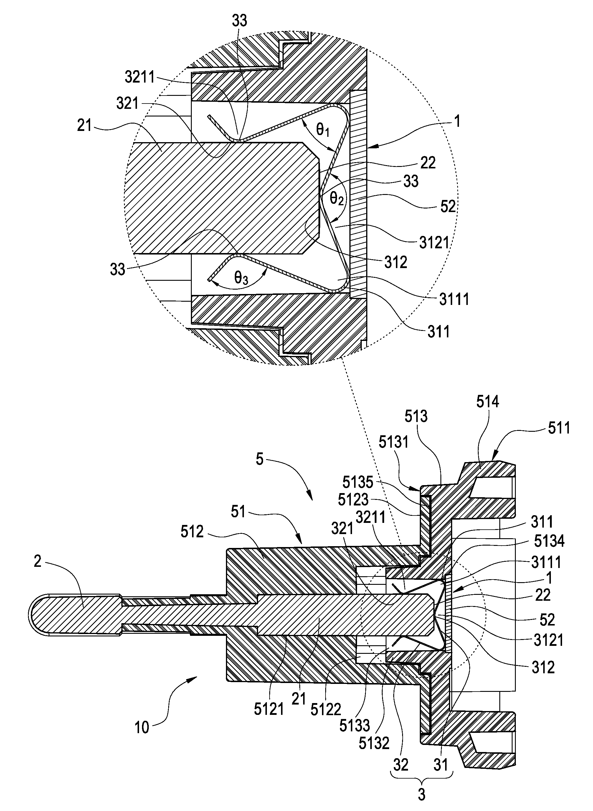
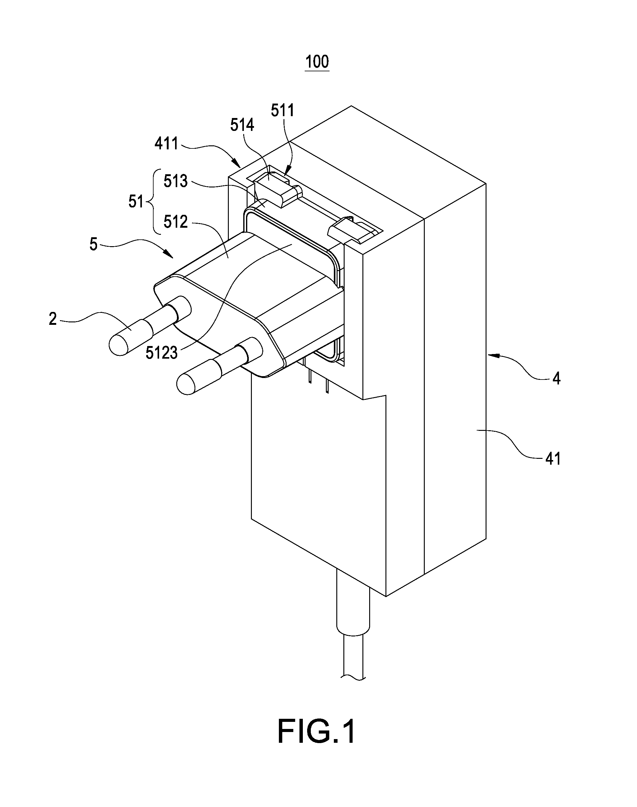
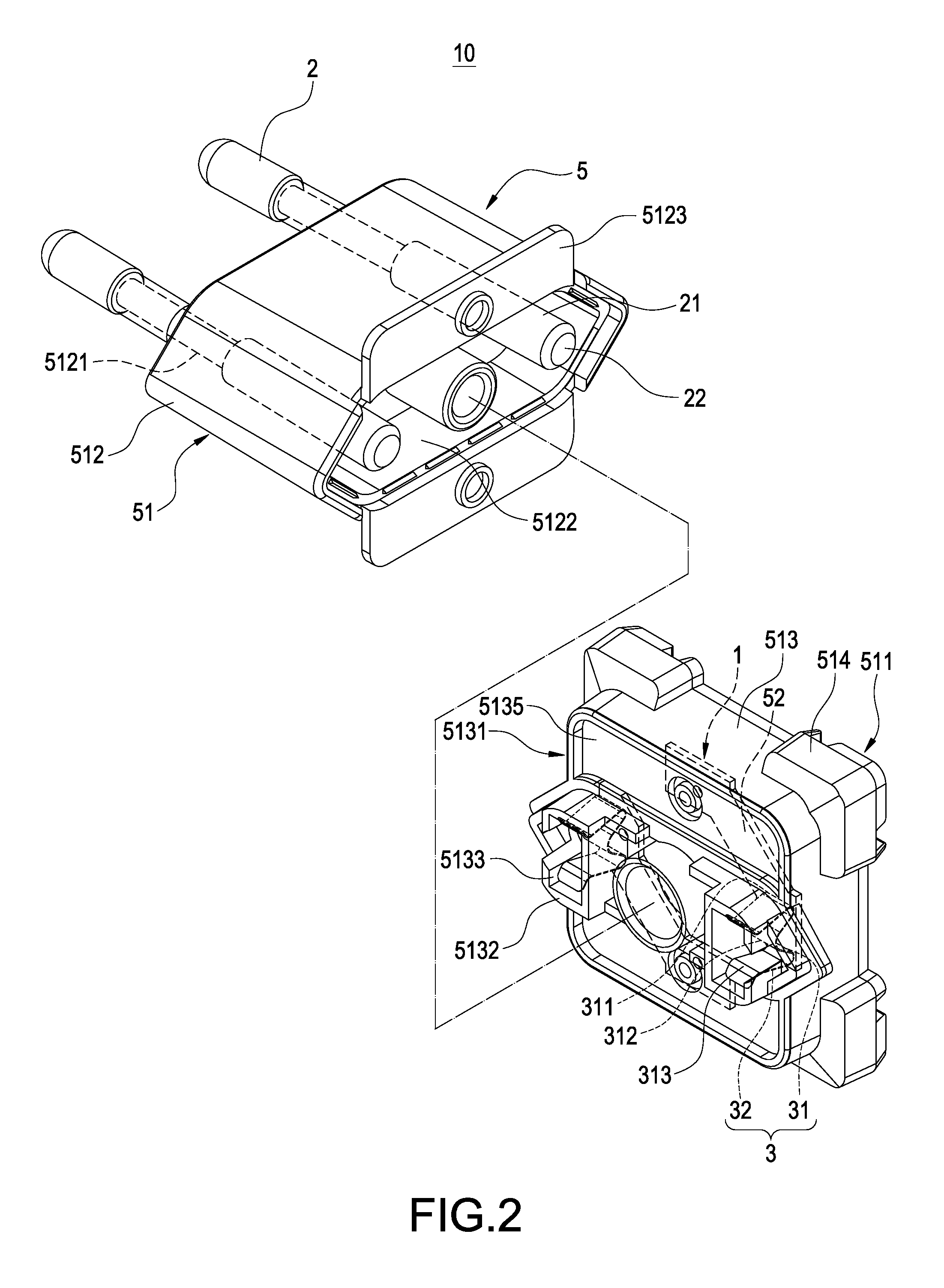
[0044]The detailed description is as follows. FIGS. 1-6 illustrate the power device 100 and the plug structure 10 of the present invention. Specifically, the plug structure 10 is a replaceable plug 5. The replaceable plug 5 further includes a plug base 51. The plug base 51 has a butting segment 511. Each of the electrical conductors 1 is a conductive sheet 52. Each of the conductive sheets 52 is fixed and exposed to the plug base 51. In other words, the lateral segment 31 is clamped between the distal end 22 and the conductive sheet 52. The first convex portion 311 contacts the conductive sheet 52. In addition, each of the pins 2 and each of the conductive elastic sheets 3 are fixed to the plug base 51.

[0045]Also, the main body 4 further includes a plurality of metal elastic sheets 43. Each of the metal elastic sheets 43 is electrically connected to the circuit board 42 and exposed to the housing 41. The housing 41 has an assembling section 411. The assembling section 411 and the bu...

second embodiment

[0055]FIG. 7 illustrates the power device 100 and the plug structure 10 of the present invention. Substantially, the plug structure 10 is a stationary plug 6. Each of the electrical conductors 1 is each of the circuits 421 formed on the circuit board 42. In other words, the lateral segment 31 is clamped between the distal end 22 and the circuit board 42. The first convex portion 311 contacts the circuit 421. Each of the pins 2 and each of the conductive elastic sheets 3 are fixed to the housing 41.

[0056]A further description is as follows. The housing 41 includes a first housing 414 and a second housing 415. The circuit board 42 is accommodated in an inside of the first housing 414. A plurality of protrusion blocks 4141 extend from the first housing 414. Each of the protrusion blocks 4141 has a perforation slot 4142. Each of the conductive portions 421 is correspondingly arranged to each of the perforation slots 4142. Each of the conductive elastic sheets 3 is accommodated in each o...


PUM


Abstract

In a power device and a plug structure, the plug structure includes an electrical conductor, a pin and a conductive elastic sheet. The pin is correspondingly arranged to the electrical conductor. The pin has a conducting portion and a distal end formed on the conducting portion. The conductive elastic sheet has a lateral segment and at least one longitudinal segment extending from the lateral segment. The lateral segment has a first convex portion and a second convex portion reversed from each other. The longitudinal segment has a third convex portion. The lateral segment is clamped between the distal end and the electrical conductor, the first convex portion contacts the electrical conductor, the second convex portion grasps and contacts the distal end, and the third convex portion contacts the conducting portion.

Description

BACKGROUND OF THE INVENTION[0001]1. Field of the Invention[0002]The present invention relates to a power device, in particular, to a power device and a plug structure thereof.[0003]2. Description of Prior Art[0004]Followed with the development of electronic technology, people extremely require electronic products for learning and working in daily life. However, these electronic products usually need a power device for power supplying or charging. This power device has a main body including a transformer structure or a circuit board. The main body has a plug fixed thereon. The plug can be inserted in a socket with complied specification, so as to drain power for operation of the electronic products.[0005]A traditional power device includes a fixed plug or a replaceable plug. Its plug generally includes a housing, a plurality of pins and a plurality of conductive sheets. The pin is fixed and partially exposed to the housing. The conductive sheet is connected to the pin via welding or ...

Claims


Application Information

Patent Timeline
Patent Type & Authority Patents(United States)
IPC IPC(8): H01R13/66H01R31/06H01R103/00
CPCH01R13/6691H01R31/065H01R2103/00
Inventor HUANG, CHIN-CHU
Owner DELTA ELECTRONICS INC
Why Eureka
Try Eureka