
Exposure control methods and apparatus for capturing an image with a moving subject region

a control method and image technology, applied in exposure control, image enhancement, instruments, etc., can solve the problems of image quality deterioration, signal-to-noise ratio worsening, and the upper limit of the amount of electrical charge accumulated in the photoelectric conversion element, so as to keep the deterioration of resolution to a minimum, the effect of wide dynamic rang

Active Publication Date: 2015-05-26
SONY SEMICON SOLUTIONS CORP
View PDF13 Cites 2 Cited by
  • Summary
  • Abstract
  • Description
  • Claims
  • Application Information

AI Technical Summary

Benefits of technology

[0031]Note that the program according to the present disclosure is a program that can be provided in a storage medium or communication medium that is provided in a computer-readable form for an information processing device or a computer system that is capable of executing various types of program code, for example. Providing this sort of program in a computer-readable form makes it possible to implement the processing according to the program in the information processing device or the computer system.
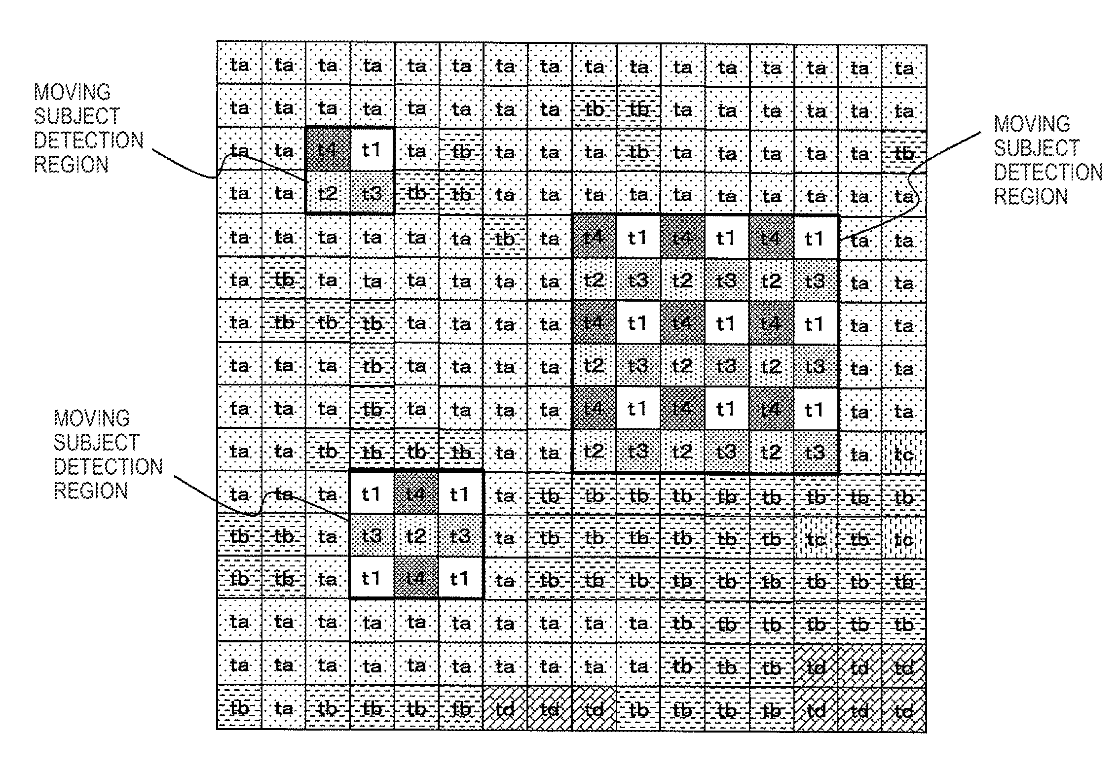
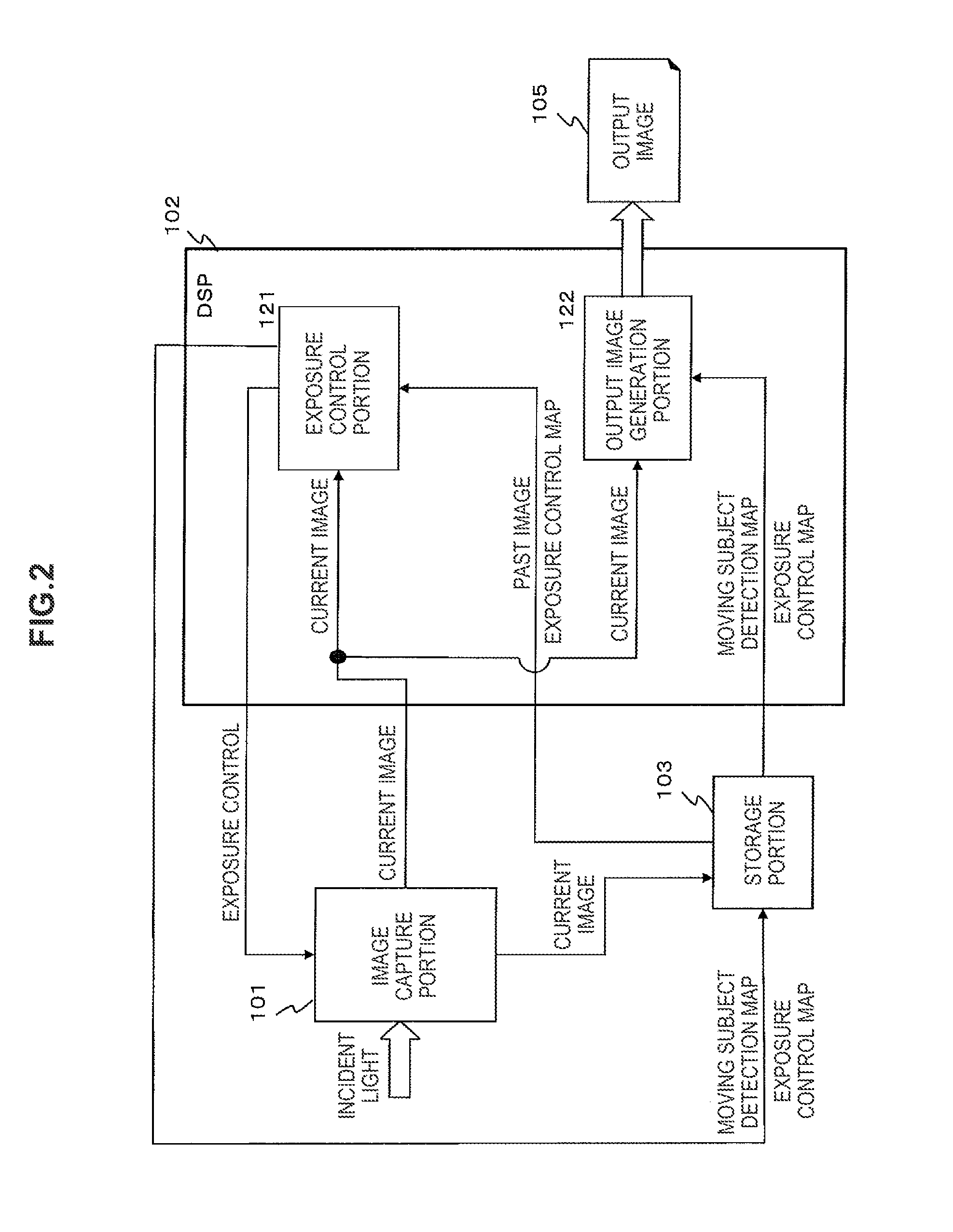
[0034]With respect to an image that is captured based on this sort of exposure time control, the output image is generated by computing pixel values with a wide dynamic range for the moving subject region, using pixel value combination processing that utilizes the pixel values of pixels for which a plurality of different exposure times have been set, and by computing pixel values with a wide dynamic range for the stationary subject region by multiplying the gain in accordance with the exposure time. This processing achieves the acquisition of a wide dynamic range image across all of the regions while keeping deterioration of the resolution to a minimum.

Problems solved by technology

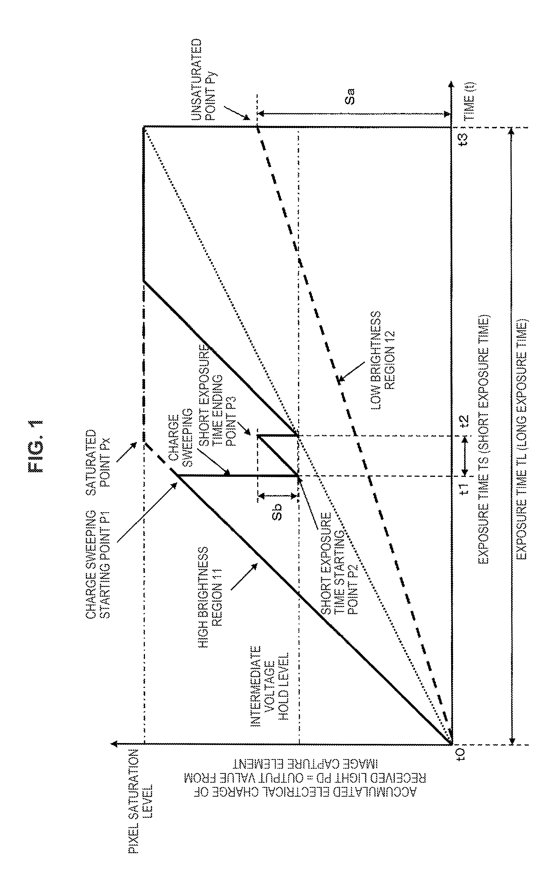
However, there is an upper limit to the amount of the electrical charge that is accumulated in the photoelectric conversion element, and when more than a fixed amount of light is received, the amount of the accumulated electrical charge reaches a saturation level, such that what are called blown out highlights, which are set at a saturated brightness level, occur in regions of the photographic subject where the brightness is greater than a fixed value.
However, in capturing an image of a subject that has a mixture of bright regions and dark regions, using a fast shutter speed means that the exposure time will not be sufficient for the dark portions, so the signal-to-noise ratio worsens, and the image quality deteriorates.
Furthermore, with the method that performs exposure control based on the brightness information for preliminarily captured images, the exposure control information that is set for the individual pixels in advance becomes erroneous information, and it becomes impossible to achieve optimum control.
Problems therefore arise, in that when the pixel that has changed from dark to bright, the exposure is much greater than what was anticipated, so the pixel becomes saturated, and when the pixel that has changed from bright to dark, the exposure is much less than what was anticipated, so the signal-to-noise ratio decreases, for example.
However, because the low sensitivity and high sensitivity sensors are arranged in a fixed pattern, the sampling sensitivity range is wider than with the known RGB sensors, so a problem occurs in that the image resolution decreases.

Method used


Image

  • Exposure control methods and apparatus for capturing an image with a moving subject region
  • Exposure control methods and apparatus for capturing an image with a moving subject region
  • Exposure control methods and apparatus for capturing an image with a moving subject region

Examples


Embodiment Construction

[0056]Hereinafter, preferred embodiments of the present disclosure will be described in detail with reference to the appended drawings. Note that, in this specification and the appended drawings, structural elements that have substantially the same function and structure are denoted with the same reference numerals, and repeated explanation of these structural elements is omitted.

[0057]Hereinafter, an image capture device, an image capture device control method, and a program according to the present disclosure will be explained with reference to the drawings. The explanation will cover the items below in order.

[0058]1. Configuration and processing of a first example of the image capture device

[0059]2. Configuration and processing of a second example of the image capture device

[0060]3. Configuration and processing of a third example of the image capture device

[0061]4. Configuration and processing of a fourth example of the image capture device

[0062]5. Summary of the configurations o...


PUM


Abstract

A moving subject detection map is generated by performing moving subject region determination based on input image information from an image capture portion, and is used to set an exposure pattern for a moving subject detected pixel region. The exposure pattern is cyclically arranged with multiple different exposure times. The exposure time for a stationary subject region is set according to the brightness of the subject. Regarding an image captured based on the exposure time control, an output image is generated by computing pixel values for a moving subject region, using pixel value combination processing that utilizes the pixel values of pixels with a plurality of different exposure times being set, and by computing pixel values for the stationary subject region by multiplying a gain according to the exposure time. This achieves the acquisition of a dynamic range image while keeping deterioration of the resolution to a minimum.

Description

CROSS REFERENCE TO RELATED APPLICATIONS[0001]The present application claims priority under 35 U.S.C. § 119 to Japanese Patent Application No. JP 2011-102914, filed in the Japan Patent Office on May 2, 2011, the entire contents of which are incorporated herein by reference.BACKGROUND OF THE INVENTION[0002]The present disclosure relates to an image capture device, an image capture device control method, and a program. In particular, the present disclosure relates to an image capture device, an image capture device control method, and a program that generate an image with a dynamic range that is wide.[0003]A solid image capture element that is used in a video camera or a digital still camera, such as a CCD image sensor or a complementary metal oxide semiconductor (CMOS) image sensor, accumulates an electrical charge that corresponds to the amount of incident light and performs a photoelectric conversion that outputs an electrical signal that corresponds to the accumulated electrical ch...

Claims


Application Information

Patent Timeline
Patent Type & Authority Patents(United States)
IPC IPC(8): G06T5/00H04N5/235H04N5/353H04N5/232G06T5/50
CPCG06T5/007H04N5/23254H04N5/2353H04N5/2355H04N5/3535G06T5/50G06T2207/10144G06T2207/20208G06T2207/20221H04N9/8205H04N23/6811H04N23/741H04N23/73H04N25/533
Inventor KURITA, TEPPEIMITSUNAGA, TOMOOJO, KENSEIKAIZU, SHUN
Owner SONY SEMICON SOLUTIONS CORP
Learn More