Capacity station activation method, radio communication apparatus, and system

a radio communication apparatus and capacity station technology, applied in the field of communication technologies, can solve the problems of exacerbated energy consumption problems, complicated actual network structure, and radio communication playing a more and more significant role in energy consumption, and achieve the effect of reducing the energy consumption of the whole system and determining more accurately

Active Publication Date: 2015-05-26
HUAWEI TECH CO LTD
View PDF14 Cites 4 Cited by
  • Summary
  • Abstract
  • Description
  • Claims
  • Application Information

AI Technical Summary

Benefits of technology

[0005]An embodiment of the present invention provides a capacity station activation method, so that a capacity station that needs to be activated can be determined more accurately, and furthermore, transmit power of an activated capacity station can be controlled, thereby reducing energy consumption of a whole system.

Problems solved by technology

As capacity and a data rate increase rapidly, radio communication plays a more and more significant role in energy consumption.
To solve a problem of a high capacity and high data requirement, an operator deploys radio networks (GERAN / UTRAN / EUTRAN) of multiple access technologies and deploys base stations (Macro / Micro / LPN) of multiple transmit power levels in the same area, which makes an actual network structure rather complicated.
High capacity and a high data rate require a base station to have high transmit power, and numerous low power nodes such as pico stations exacerbate an energy consumption problem undoubtedly.
In fact, The prior art has the following disadvantages: when the coverage station is heavy-loaded, generally, loads are not evenly distributed in a coverage range, but are centralized in some areas.
In application, an existing capacity station activation solution may have the following problems: After multiple capacity stations are activated simultaneously and work at a maximum transmit power level, a load of the coverage station may be reduced to an extremely low level or the coverage station is even in a zero-load state, which is not useful for enhancing overall energy efficiency of a network actually.

Method used


Image

  • Capacity station activation method, radio communication apparatus, and system
  • Capacity station activation method, radio communication apparatus, and system
  • Capacity station activation method, radio communication apparatus, and system

Examples


first embodiment

[0037]In the present invention, a cell activation solution in which both a macro base station and a pico station are EUTRAN base stations.

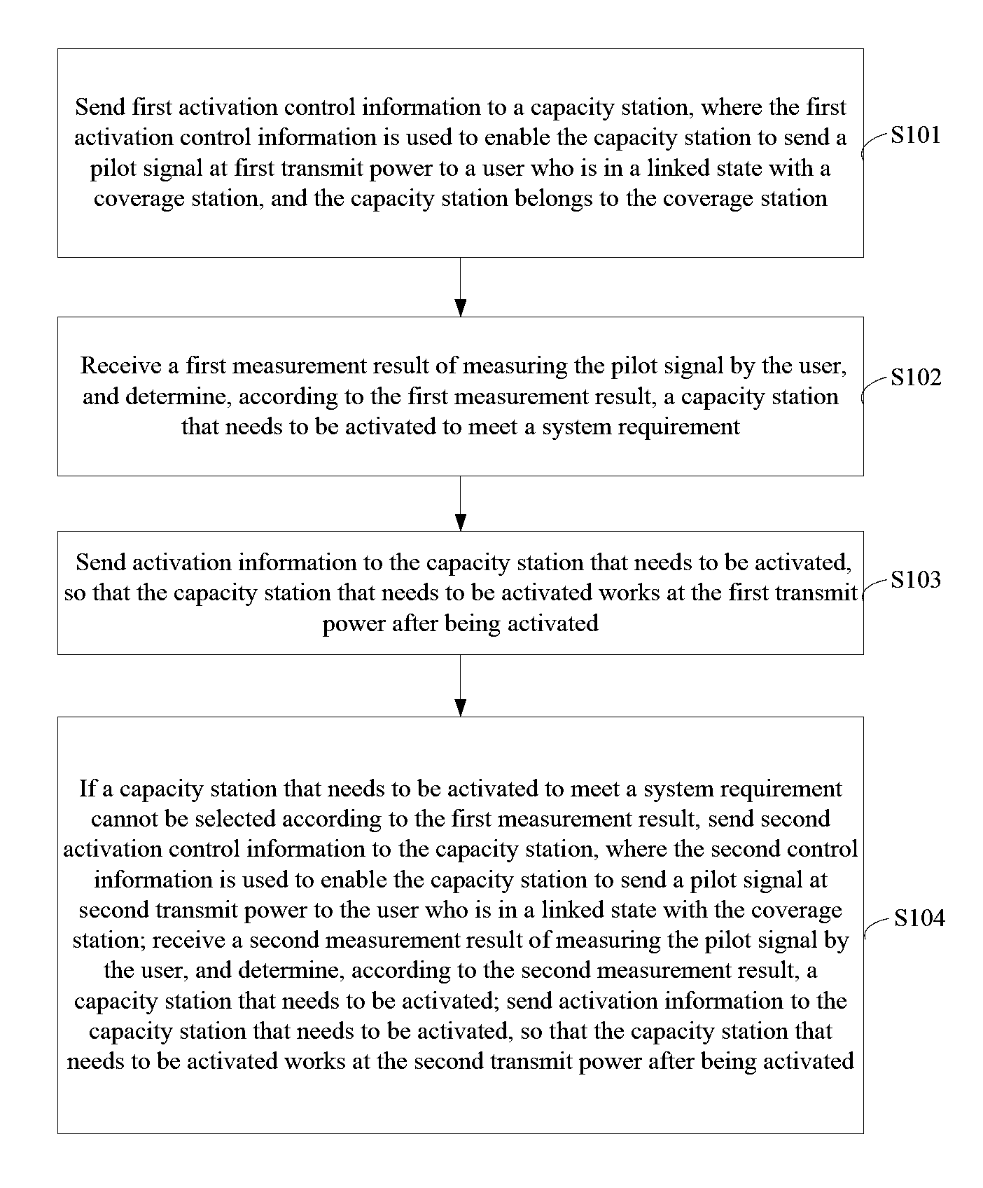
[0038]Step 1: When the number of users who are in a linked state with a macro base station exceeds a preset threshold Cthreshold (a first threshold), the macro base station instructs a pico station in a capacity station set S to send a pilot signal in a time of T at a pilot power level of Plow, and may also send a synchronization signal (the pico station stops sending and returns to a dormant state after sending the pilot signal in the time of T), and configures a user who is in a linked state with the macro base station to perform measurement and reporting on the pilot signal sent by the pico station in S.

[0039]Step 2: The macro base station performs the following operations according to a measurement result reported by the user: For each pico station Hi (i=1, 2, . . . , N), count the number of macro base station users that meet a handover condit...

second embodiment

[0052]the present invention discloses a cell activation solution in which a macro base station is a UTRAN base station, and a pico station is an EUTRAN base station. The macro base station provides basic network coverage. The pico station is deployed in a pico station area in a coverage range of the macro base station to boost capacity and is completely covered by the macro base station. When a part or all of pico stations are in a dormant state and the macro base station is heavy-loaded, the pico stations may be activated by adopting the technical solution described in the present invention.

[0053]In this embodiment, the pico station uses two pilot transmit power levels in an activation decision process, which are Plow and Pmax respectively, where Plow is a certain preset power level that is lower than Pmax, and Pmax may be maximum pilot transmit power of the pico station.

[0054]Main steps in the technical solution according to the second embodiment are as follows:

[0055]Step 1: When ...

third embodiment

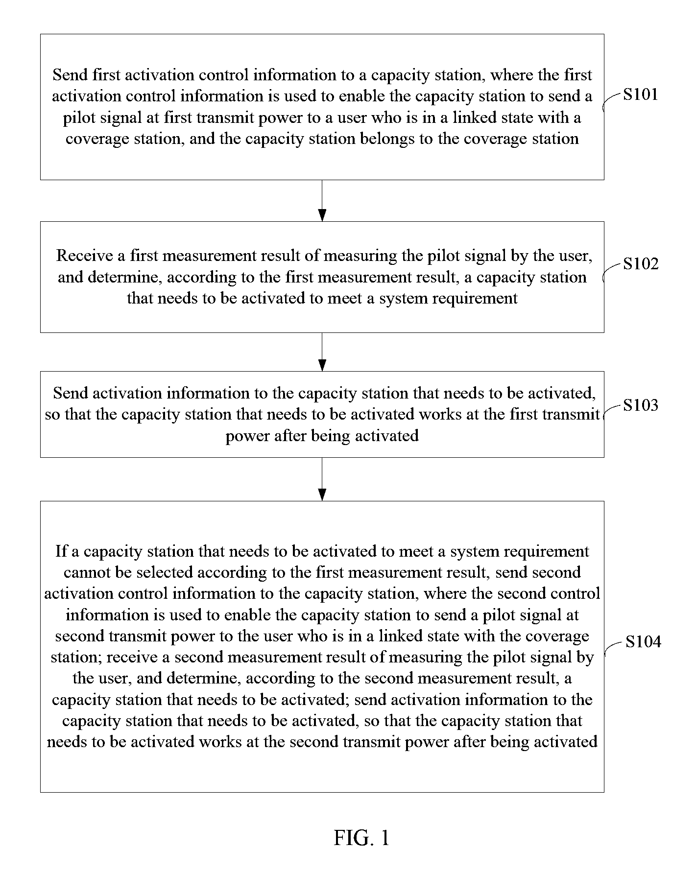
[0069]A network scenario of the present invention is as follows: A base station A on a frequency f1 provides basic network coverage for a certain area, and a base station B / C / D on a frequency f2 overlaps with the base station A in coverage. The base station A and the base station B / C / D may be base stations of different standards, and may also be base stations of the same standard but different frequencies. A part or all of base stations B, C, and D are in a dormant state to save power. When the base station A is heavy-loaded, the technical solution disclosed in the present invention may be used to activate a part or all of base stations B, C, and D that are in a dormant state, enable them to work at proper pilot transmit power, and meanwhile, ensure that a load of the base station A is reduced to a proper level.

[0070]It is assumed that when the number of users who are in a linked state with the base station A on the frequency f1 exceeds a first threshold, a preset threshold Cthresho...


PUM


Abstract

Embodiments of the present invention provide a capacity station activation method and system. The method includes: A coverage station sends activation control information to a capacity station, where the activation control information is used to enable the capacity station to send a pilot signal to a user in a power increasing manner; receives a measurement result of measuring the pilot signal by the user; determines, according to the measurement result, a capacity station that needs to be activated to meet a system requirement; and sends activation information to a determined capacity station that needs to be activated to activate the capacity station. With the capacity station activation method and system in the embodiments of the present invention, a capacity station that needs to be activated can be determined more accurately, and furthermore, transmit power of an activated capacity station can be controlled, thereby reducing energy consumption of a whole system.

Description

CROSS-REFERENCE TO RELATED APPLICATIONS[0001]This application is a continuation of International Patent Application No. PCT / CN2012 / 072995, filed on Mar. 26, 2012, which claims the priority of Chinese Application No. 201110111754.0, filed on Apr. 29, 2011, both of which are hereby incorporated by references in their entities.FIELD OF THE INVENTION[0002]Embodiments of the present invention relate to communications technologies, and in particular, to a base station activation and power control method, an apparatus, and a radio communication system.BACKGROUND OF THE INVENTION[0003]As capacity and a data rate increase rapidly, radio communication plays a more and more significant role in energy consumption. To solve a problem of a high capacity and high data requirement, an operator deploys radio networks (GERAN / UTRAN / EUTRAN) of multiple access technologies and deploys base stations (Macro / Micro / LPN) of multiple transmit power levels in the same area, which makes an actual network struct...

Claims


Application Information

Patent Timeline
Patent Type & Authority Patents(United States)
IPC IPC(8): H04M3/00H04W40/00H04W16/08H04W16/32H04W24/02H04W28/02H04W28/08H04W52/02H04W52/04
CPCH04W28/0289H04W52/0219H04W52/04H04W52/0206Y02B60/50H04W16/08H04W16/32H04W24/02H04W28/0284H04W28/08Y02D30/70
Inventor ZHANG, SHUNQINGXU, XIUQIANGCHEN, YAN
Owner HUAWEI TECH CO LTD
Why Eureka
Try Eureka