Range of motion machine and method and adjustable crank

Active Publication Date: 2015-06-02
LAMPERT DAVID L
View PDF51 Cites 45 Cited by
  • Summary
  • Abstract
  • Description
  • Claims
  • Application Information

AI Technical Summary

Benefits of technology

[0003]A principal feature of the machine is that motor-driven cranks for exercising the arms or legs of the user through a circle of rotation have crank arms adjustable in length to change the circle size. The crank arm length may be changed whether the cranks are stopped or are rotating. Typically, a use

Problems solved by technology

Previous machines have cranks which are fixed in length or have a manual adjustment that can be changed only when stopped, and which are

Method used


Image

  • Range of motion machine and method and adjustable crank
  • Range of motion machine and method and adjustable crank
  • Range of motion machine and method and adjustable crank

Examples


Embodiment Construction

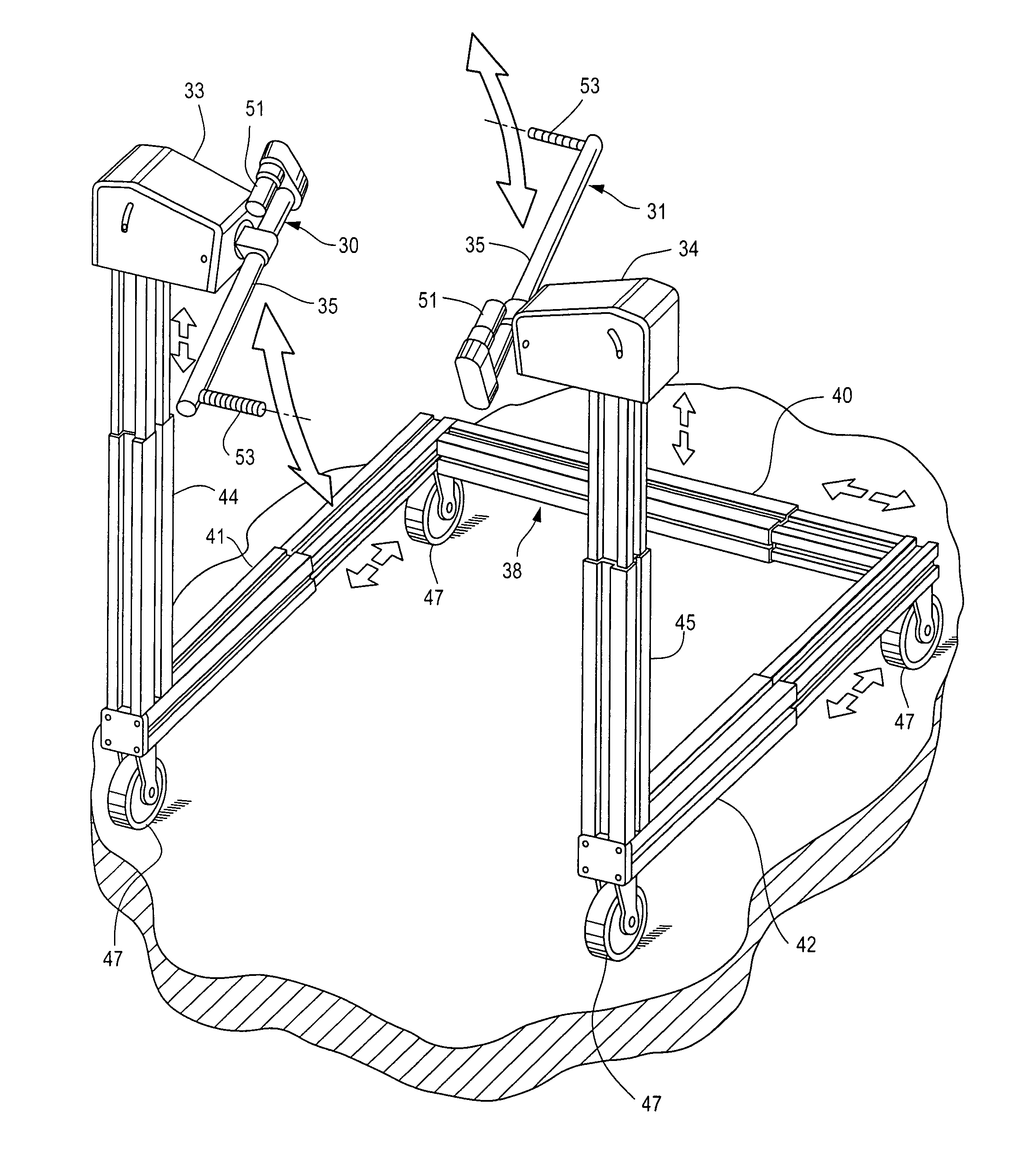
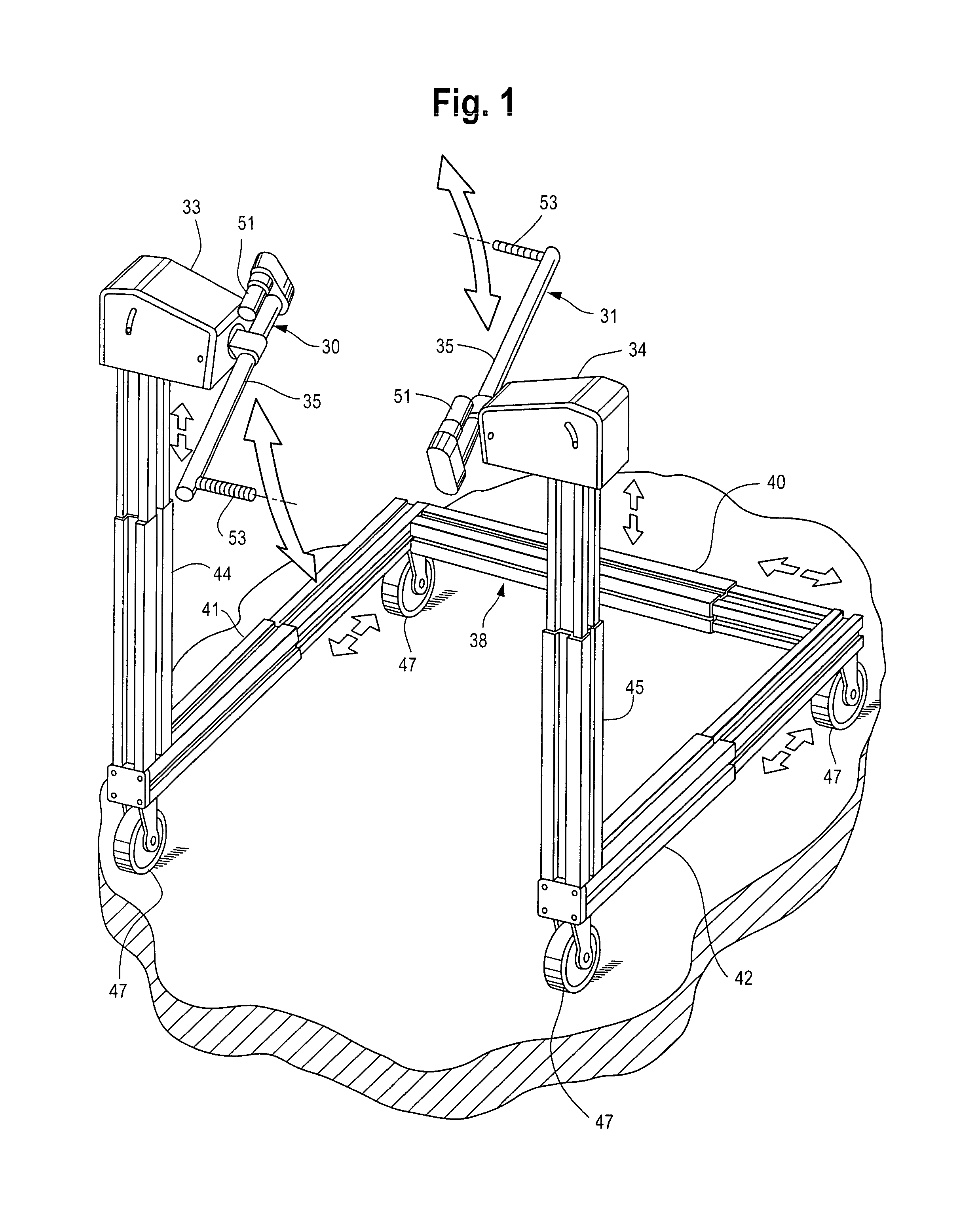
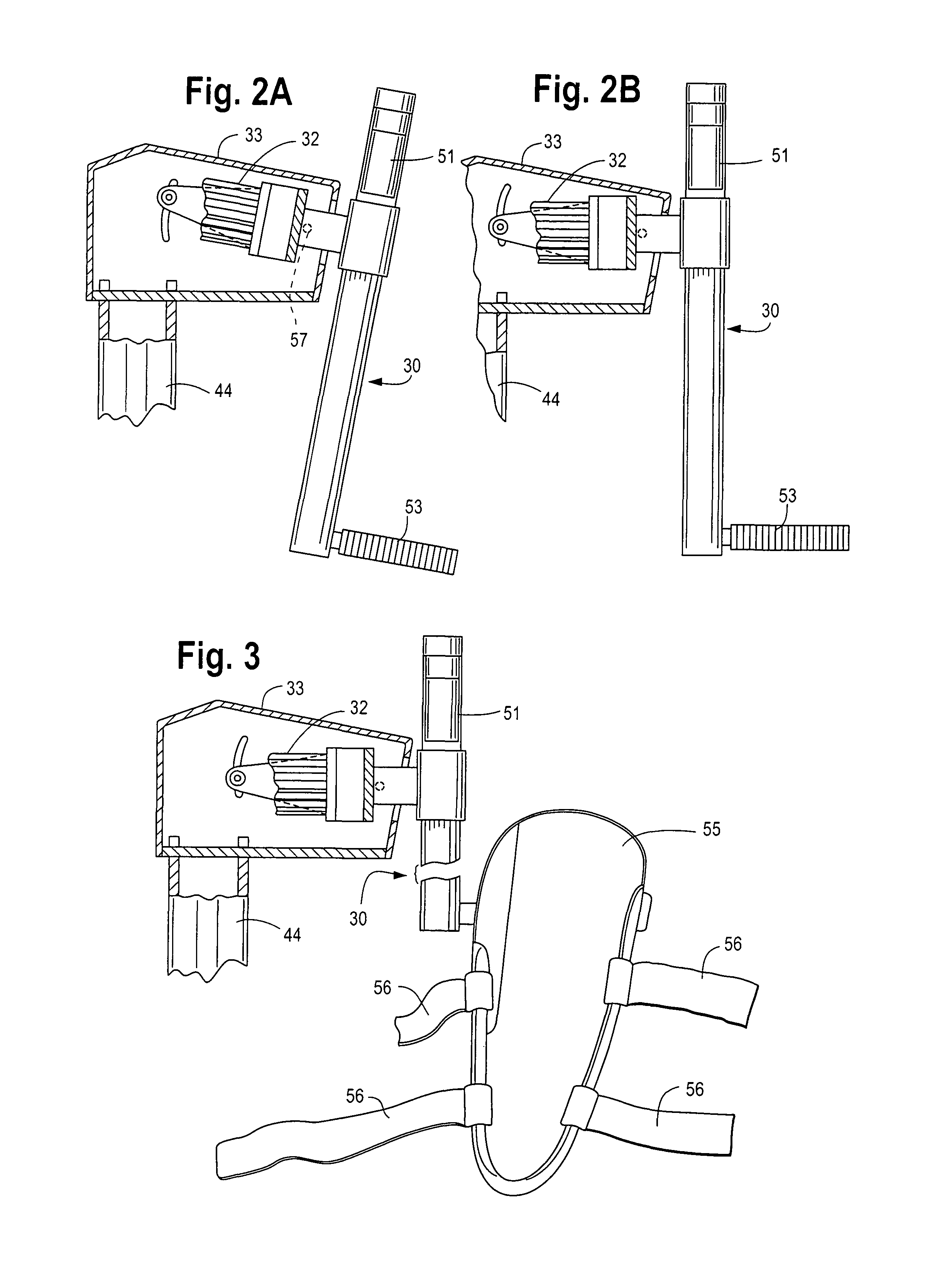
[0043]A first embodiment of the ROM machine particularly suited for use in a hospital or rehabilitation facility where the user may be confined to bed and in other environments, is shown in FIGS. 1-5B. A pair of opposed cranks 30, 31 are directly driven by separate electric motors, as motor 32, FIGS. 2A, 2B in housings 33, 34. The motor speed is adjustable and may, for example, range from barely moving to 40 r.p.m. The motor housing and motor control will be discussed below. The cranks have planes of rotation which define a user location 36 between them, FIGS. 4A, 4B. The user location may, for example, be a hospital bed or a padded bench. A U-shaped frame 38 has a base 40 and legs 41, 42. Pedestals44, 45, one at the end of each frame leg remote from base 40, have the crank motor housings 33, 34 and cranks 30, 31 mounted at the top. The crank motor housings are sometimes referred to hereafter as crank heads. The frame 38 has swiveled, locking caster wheels 47 and may readily be move...


PUM


Abstract

A range of motion machine having two or four cranks driven directly by motors without exposed gears or chains. The speed and direction of crank rotation and the length of the crank arms may be varied with electronic controls. Crank arm length may be varied whether the crank is stationary or rotating. The cranks and motors are mounted at the top of pedestals which are adjustable in height.

Description

BACKGROUND OF THE INVENTION[0001]It is known to provide exercise machines with motor driven cranks which are engaged by hands and / or feet of the user. Such machines may be used passively, as to provide movement of the arms and / or legs of a person incapacitated in some way, or actively where the user will try to advance or retard the rotation of the cranks, building muscle. Previous machines have cranks which are fixed in length or have a manual adjustment that can be changed only when stopped, and which are connected with a drive motor through chains, belts, and / or gears that are noisy, risk injury to the user and require guards or shields.BRIEF SUMMARY OF THE INVENTION[0002]This invention provides a Range of Motion (ROM) machine which will increase the range of motion of the user's arms and legs in addition to affording exercise and building muscle. Several embodiments are disclosed.[0003]A principal feature of the machine is that motor-driven cranks for exercising the arms or legs...

Claims


Application Information

Patent Timeline
IPC IPC(8): A63B24/00A63B21/00
CPCA63B24/00A63B21/00127A61H1/0214A61H1/0255A61H1/0274A61H2201/0142A61H2201/0176A61H2201/0192A61H2201/1215A61H2201/5002A61H2203/0406A61H2203/0431A61H2203/0437A61H2203/0456A63B21/00076A63B21/015A63B23/04A63B23/12A63B2023/003A63B2208/0204A63B2208/0228A63B2208/0252A63B21/4033A63B21/4035A63B23/035A63B24/0087A63B21/4049A63B21/15A63B21/153A63B21/154
Inventor LAMPERT, DAVID L.BRIGGS, STEPHENCLER, EDWARD WILLIAMHOREIN, DANIEL DAVIDLILLY, BRIAN P.RUND, BENJAMIN BERTON
Owner LAMPERT DAVID L
Why Eureka
Try Eureka