Cursor control device

a technology of cursors and control devices, applied in the field of cursor control technology, can solve problems such as carpal tunnel syndrome, wrist pain, and a lot of pressure on the underside of the wrists

Active Publication Date: 2015-06-02
LIANG HSU +1
View PDF12 Cites 1 Cited by
  • Summary
  • Abstract
  • Description
  • Claims
  • Application Information

AI Technical Summary

Benefits of technology

[0008]The present invention has been accomplished under the circumstances in view. It is one object of the present invention to provide a cursor control device, which eliminates the drawbacks of the aforesaid conventional measures
[0010]Further, the sensor module of the circuit module is mounted on the outside of the carrier frame at one lateral side corresponding to the opening of the carrier frame for detecting the direction and amount of movement of the rolling roll. It simply needs to provide a space below the carrier frame for allowing vertical movement of the carrier frame and for accommodating the balance bar. Therefore, the vertical height of the cursor control device can be minimized and, outside dust will not enter the opening to cover the sensor module, assuring a high level of sensing accuracy.
[0011]Further, a balance bar is pivotally supported on bottom support members of the carrier frame, having two end pins thereof respectively pivotally coupled to respective pivot connectors at the module holder. Therefore, the balance bar keeps the rolling roll and the carrier frame in balance for allowing the carrier frame to be moved downwards smoothly. If the carrier frame is made from a non-hard material (plastics or rubber), the balance bar will support the carrier frame in shape, keeping the carrier frame straight and allowing rotation or axial displacement of the rolling roll smoothly.
[0012]Further, the carrier frame can be prepared from POM, PTFE or any other self-lubricating material to reduce friction. Further, supplementary elements may be used to facilitate rotation of the rolling roll in the rotation groove.
[0013]Further, the rolling roll can be a solid roll. Alternatively, the rolling roll can be a tubular roll having an axial through hole extending through the two distal ends thereof for accommodating weights to adjust the total weight of the rolling roll. Further, a magnetically permeable core member may be fitted into the axial through hole of the rolling roll. Further, magnetic members may be affixed to the carrier frame to attract the magnetically permeable core member in the axial through hole of the rolling roll, securing the rolling roll to the carrier frame and avoiding falling of the rolling roll out of the carrier frame accidentally due to an excessive amount of applied force during operation of the cursor control device.

Problems solved by technology

However, when going to move the computer mouse over a big area, the user must lift the wrist from the desk or mouse pad.
Excessive or improper use of a computer may cause pain in the wrist (the so-called carpal tunnel syndrome).
However, leaning the wrists on a wrist rest for long periods can put a lot of pressure on the undersides of the wrists.
This may cause carpal tunnel syndrome to develop.
Further, an improperly used wrist rest may actually cause more repetitive stress injuries for those who mouse for extended periods of time.

Method used


Image

  • Cursor control device
  • Cursor control device
  • Cursor control device

Examples


Embodiment Construction

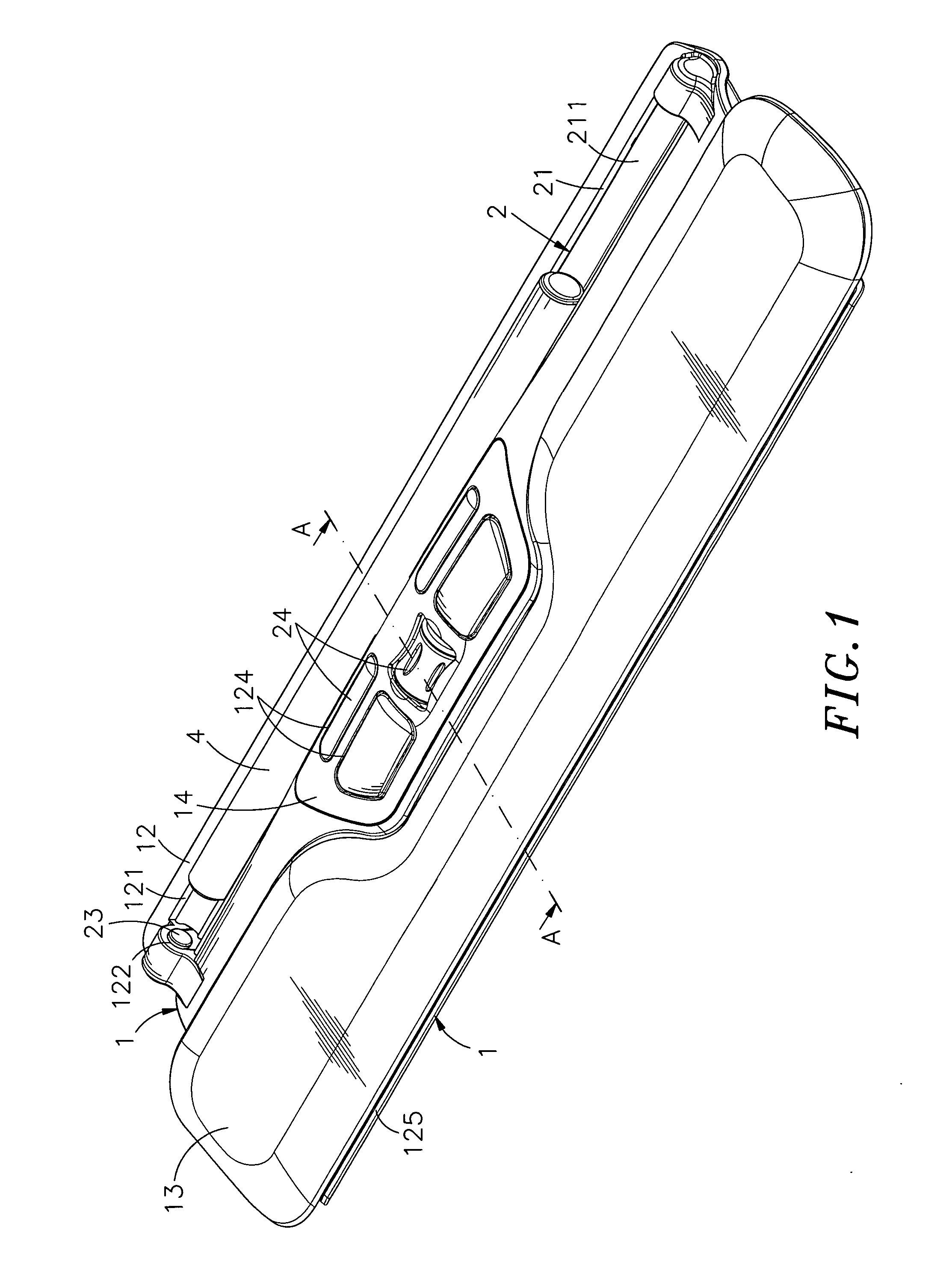
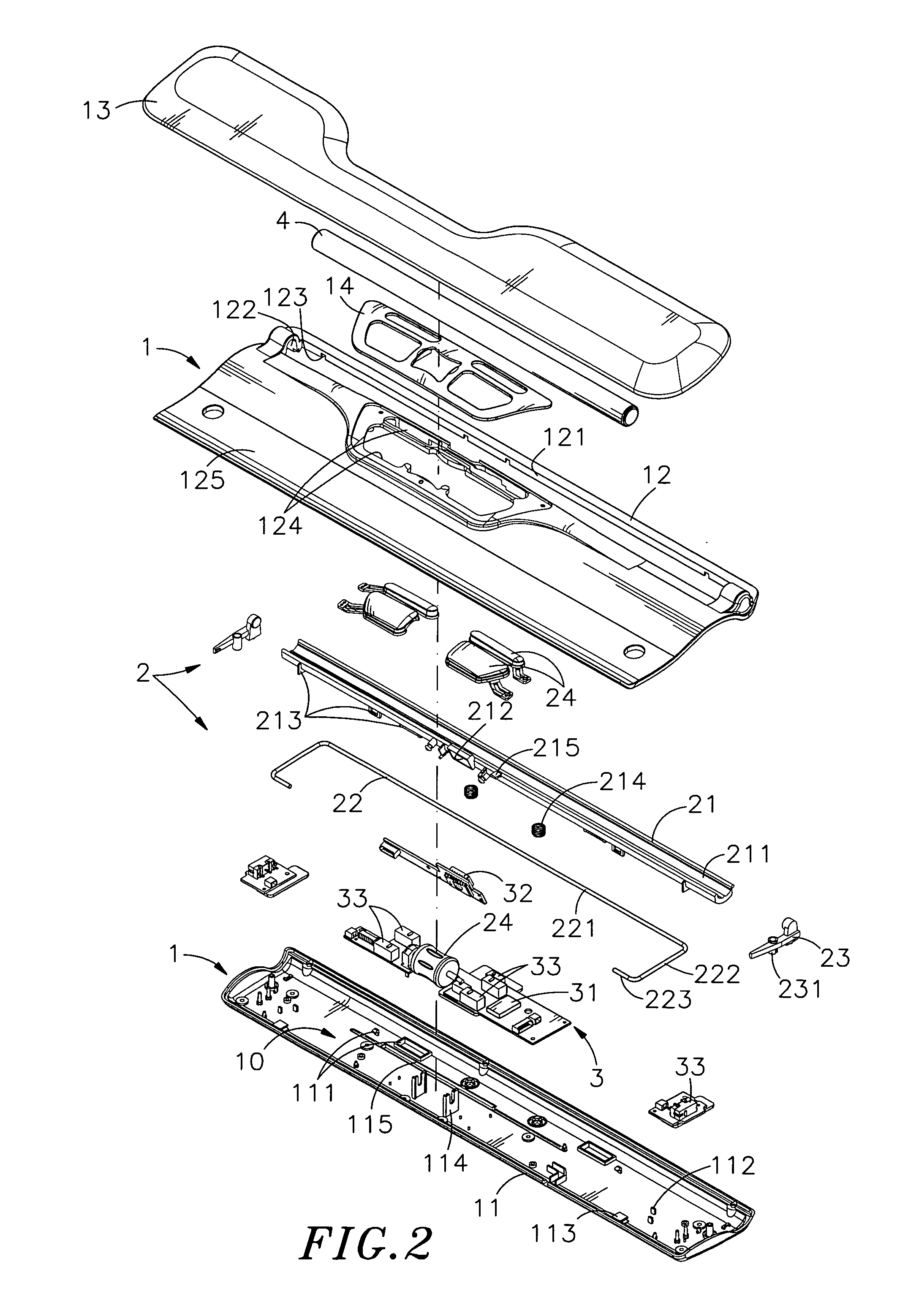
[0023]Referring to FIGS. 1˜5, a cursor control device in accordance with the present invention is shown comprising a module holder 1, an operation module 2, a circuit module 3 and a rolling roll 4.

[0024]The module holder 1 comprises a first holder shell 11 and a second holder shell 12. The first holder shell 11 and the second holder shell 12 define therebetween an accommodation space 10. The first holder shell 11 has a plurality of limiters 111 disposed in the accommodation space 10 at one lateral side, a plurality of locating members 112 and pivot connectors 113 symmetrically disposed near two distal ends of the first holder shell 11 within the accommodation space 10 at the other lateral side opposite to the limiters 111, a plurality of pivot supports 114 spaced between the locating members 112 and the pivot connectors 113 and a groove 115 disposed between the limiters 111 and the pivot supports 114. The second holder shell 12 has a slot 121 cut through the top and bottom walls the...


PUM


Abstract

A cursor control device having a low profile characteristic is disclosed to include a module holder defining an accommodation space and a slot, an operation module having a carrier frame mounted in the accommodation space and inserted through the slot, a rolling roll rotatably and axially movably set in a rotation groove on the carrier frame outside the module holder, and a circuit module having a microprocessor and a sensor module mounted in carrier frame outside the rotation groove and electrically connected with the microprocessor for detecting the direction and amount of movement of the rolling roll. The rolling roll can be directly removed from the carrier frame by the user for cleaning or for a replacement.

Description

[0001]This application claims the priority benefit of Taiwan patent application number 098203274, filed on Mar. 4, 2009.BACKGROUND OF THE INVENTION[0002]1. Field of the Invention[0003]The present invention relates to cursor control technology and more particularly, to a cursor control device, which uses a sensor module to detect the direction and amount of movement of a rolling roll that is rotatably mounted in a rotation groove on a carrier frame and can be removed from the carrier frame directly by the user for cleaning or for weight adjustment.[0004]2. Description of the Related Art[0005]Following fast development of modern technology and the electronic industry, many kinds of consumer electronics, such as computer, mobile telephone, digital camera, personal digital assistant and etc., have entered into our daily life. Further, following popularization of network, people may use the internet to search for information on the World Wide Web. Through the internet, people can watch o...

Claims


Application Information

Patent Timeline
Patent Type & Authority Patents(United States)
IPC IPC(8): G06F3/033G06F3/03G06F3/0354G06F3/0362G06F3/042G06F3/0481G06F3/0485H01H19/14H01H25/00
CPCH01H25/008G06F3/0354G06F3/0485G06F3/03543G06F3/033G06F3/04812G06F3/0362G06F3/0304G06F3/0312G06F3/042H01H2019/146
Inventor CHIANG, HSIAO-LONG
Owner LIANG HSU
Why Eureka
Try Eureka