
Coupling method for resonant diathermy and other bio-tissue heating applicators

a diathermy and biotissue technology, applied in the field of diathermic devices, can solve the problems of unintentional capacitive coupling on the secondary coil (due to motion, treatment recipients) not being effectively prevented from adversely affecting the characteristics of the equivalent resonant circuit, and achieve the effect of reducing the common-mode rejection ratio (cmrr) of the circuit and ensuring the effect of resonant hea

Active Publication Date: 2015-06-09
VIATHERM THERAPEUTICS LLC
View PDF16 Cites 0 Cited by
  • Summary
  • Abstract
  • Description
  • Claims
  • Application Information

AI Technical Summary

Benefits of technology

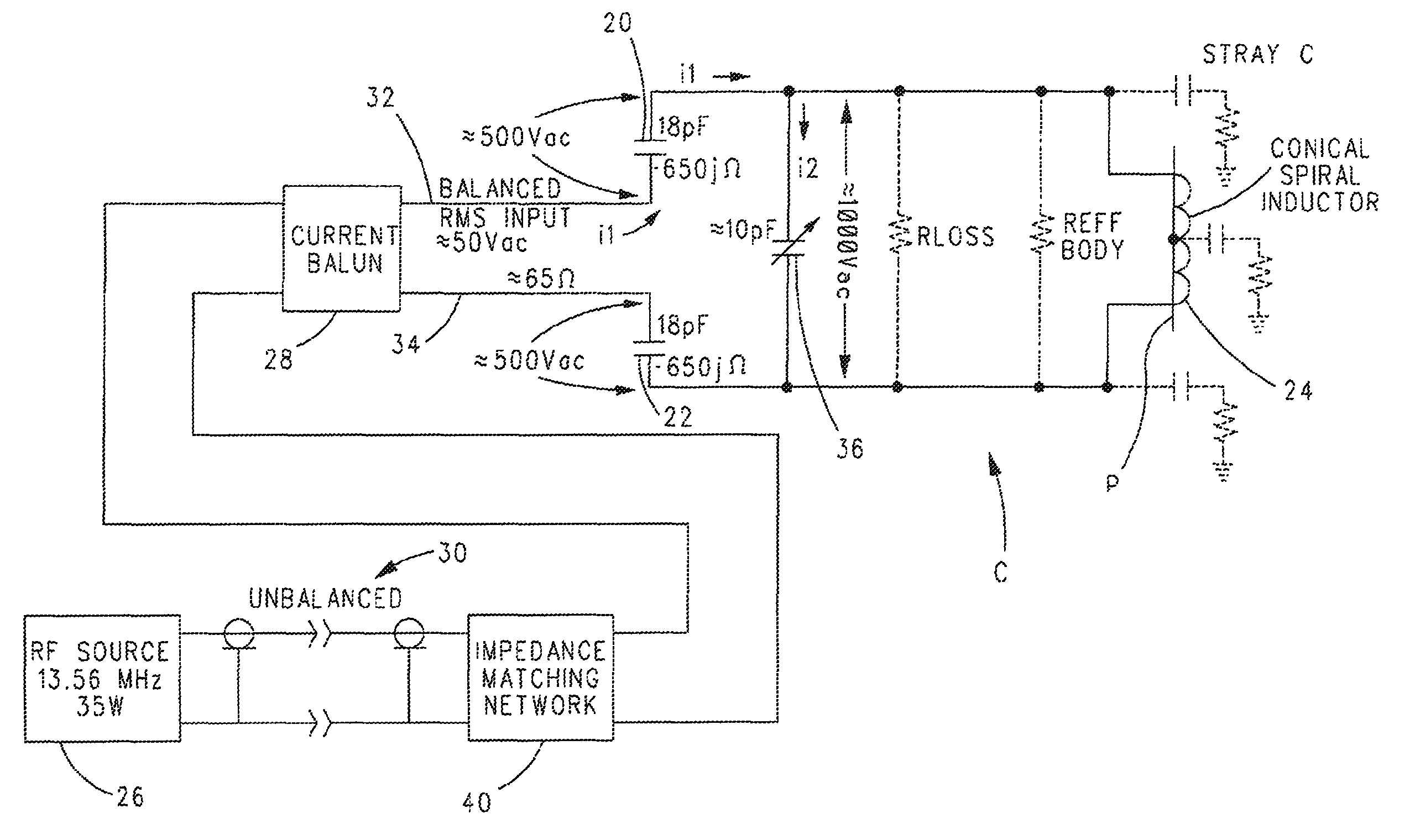
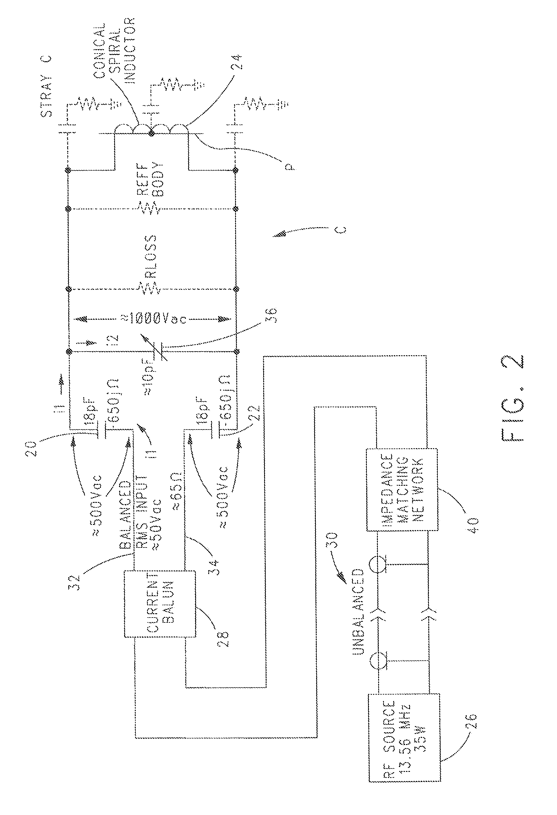
[0022]The present invention overcomes the problem in the art of resonant diathermic heating by disclosing a method and means for reliably and efficiently boosting the common-mode rejection ratio (CMRR) of the circuit driving the secondary coil. More specifically, the present invention provides a method and system which avoids the foregoing problems and others by eliminating inductive coupling. The present invention replaces inductive coupling with capacitive coupling done in a symmetrical manner to each end of the secondary winding.
[0028]As a further feature, the present invention teaches the application of a balun in such a way that the driving device is free to adopt a ground point in whatever manner is dictated by the circumstances, without causing penalties in stray conducted radiation, which is not taught by the prior art.
[0029]As a further feature of the present invention, capacitors are used to establish the needed coupling. Capacitors have the advantage, as is known in the art, that as passive devices they can be specified accurately and remain stable over time.

Problems solved by technology

However, unintentional capacitive coupling on the secondary coil (due to motion or other interaction of the treatment recipient) is not effectively prevented from adversely affecting the characteristics of the equivalent resonant circuit.

Method used


Image

  • Coupling method for resonant diathermy and other bio-tissue heating applicators
  • Coupling method for resonant diathermy and other bio-tissue heating applicators
  • Coupling method for resonant diathermy and other bio-tissue heating applicators

Examples


Embodiment Construction

[0052]The present invention will now be described with reference to the accompanying figures where like reference numerals correspond to like elements.

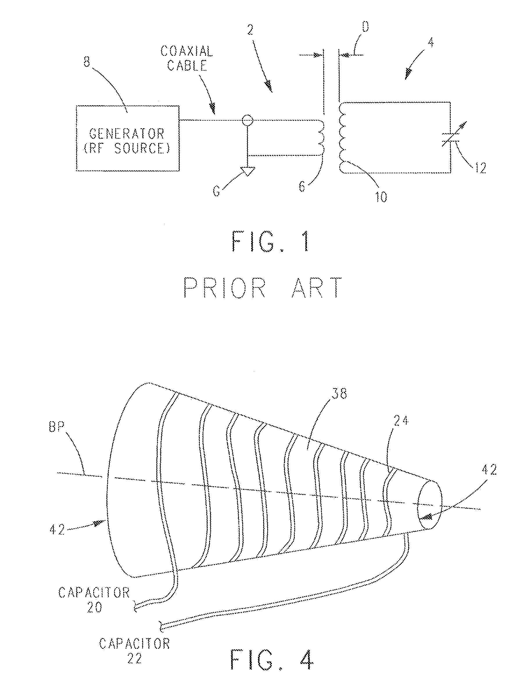
[0053]With reference to FIG. 2, in the present invention, capacitive coupling with two identical (or substantially identical) capacitors 20 and 22 is used to achieve symmetrical (or substantially symmetrical) coupling to each end of a circuit C, comprised of a conical cylindrical (or cone-shaped) spiral coil 24 and an optional parallel tuning capacitor 36, that is utilized for the application of RF diathermy treatment to a patient P. The present invention relies on the specific values of capacitors 20 and 22 to achieve the capacitive coupling desired.

[0054]Capacitive coupling is done in a manner symmetrical to each end of coil 24. The values of coupling capacitors 20 and 22 can be selected to achieve the desired coupling and since they are electrically symmetrically placed, the voltage across each capacitor 20 and 22 is identical (or ...


PUM


Abstract

A diathermy apparatus includes a cylindrical coil (24) defining an opening (42), a pair of capacitors of substantially similar capacitance (20 and 22), each capacitor connected to one end of the coil, an RF signal source (26), and a balun (28) connected between the RF signal source (26) and the pair of capacitors (20 and 22). The balun (28) is operative for converting an unbalanced signal received from the RF signal source (26) into a balanced signal supplied to coil (24) via the pair of capacitors (20 and 22). Desirably, the cylindrical coil is a conical cylindrical (or cone-shaped) spiral coil.

Description

CROSS REFERENCE TO RELATED APPLICATIONS[0001]The present application claims priority to U.S. Provisional Patent Application No. 61 / 476,514, filed Apr. 18, 2011, which is incorporated herein by reference.BACKGROUND OF THE INVENTION[0002]1. Technical Field[0003]This invention relates to diathermic devices used for therapeutic heating and, in particular, to systems for administering the application of diathermic energy in a controlled way.[0004]2. Background Art[0005]Resonant-circuit diathermic devices used for therapeutic heating (as opposed to non-resonant devices which have been eclipsed) represent a growing market. These devices have the ability to provide accurate warming of body areas without heating the intervening skin. U.S. Pat. No. 4,685,462, for example, describes warming of the body in the treatment of severe hypothermia, wherein a victim may be warmed internally in order to minimize the risk of cardiac arrest or skin burns. U.S. Pat. No. 6,094,599 describes the use of such...

Claims


Application Information

Patent Timeline
Patent Type & Authority Patents(United States)
IPC IPC(8): A61F2/00A61F7/00A61N2/02A61N5/00A61B18/12
CPCA61F7/007A61N2/02A61N5/00A61B18/1206
Inventor UNETICH, ROBERT M.
Owner VIATHERM THERAPEUTICS LLC
Learn More