
Interface between a security module and a host device

a security module and host device technology, applied in the direction of aperture leaage reduction, electrical apparatus construction details, instruments, etc., can solve the problems of increasing the frequency of security modules may be susceptible to interference, electromagnetic interference or emi, etc., to reduce the amount of electromagnetic interference

Active Publication Date: 2015-06-09
NAGRAVISION SA
View PDF15 Cites 0 Cited by
  • Summary
  • Abstract
  • Description
  • Claims
  • Application Information

AI Technical Summary

Benefits of technology

The present invention aims to decrease the levels of electromagnetic interference (EMI) that can be detected from outside a device when it is connected to a security module. This is important because EMI can interfere with the proper functioning of electronic components within the host device. The invention achieves this while still allowing easy physical access to the host device by the security module, and without the need for expensive screening layers. Overall, the invention reduces manufacturing costs associated with host devices that require security modules.

Problems solved by technology

With the increasing use of higher and higher signal frequencies in the operation of electronic circuits, the problems related to electromagnetic interference or EMI are becoming more acute.
Similarly, a security module may be susceptible to interference by sufficiently strong electromagnetic fields generated externally to the security module for the purpose of influencing the operation of the security module and / or card reader during operation.
Such interference, generated either externally or internally by the security module or any of the other circuitry within the host during operation, is known as electromagnetic interference or EMI.
Indeed, there are industry-standard limits placed on electronic circuits relative to the amount of electromagnetic radiation such circuits are allowed to generate.
However, in the case of a host device designed to receive a security module via a slot or port, it is difficult to prevent EMI from escaping since the port presents a discontinuity in the enclosure and therefore a discontinuity in the shielding thereby exposing an area where EMI may escape.

Method used


Image

  • Interface between a security module and a host device
  • Interface between a security module and a host device
  • Interface between a security module and a host device

Examples


Embodiment Construction

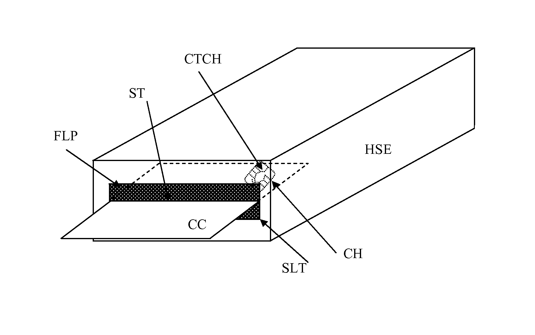
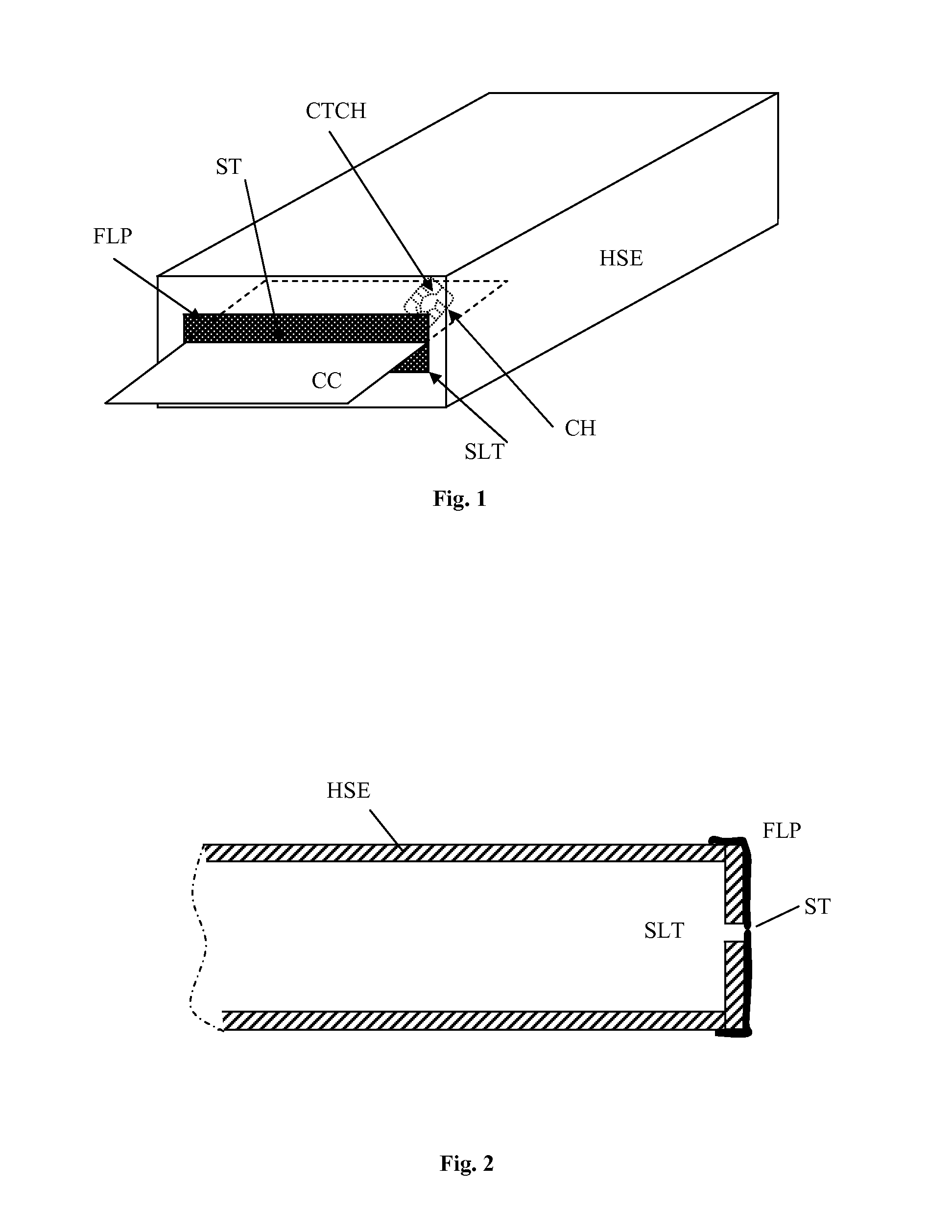
[0027]In a system comprising a host device and a detachable security module (CH), wherein the a card reader within the host device is adapted to form an interface with the detachable security module (CH), at least some of the signals in the interface will carry high frequency signals susceptible to producing or being affected by electromagnetic interference. Depending on the design of the host device and any components therein, there may be further areas within the host device which are susceptible to EMI. According to an embodiment of the present invention, techniques are employed to provide means to minimise the amount of EMI from penetrating from the interior of the host device to the exterior or from the exterior to the interior. For example, any connections carrying signals having a frequency component are kept as short as possible as it is known that the length over which a high frequency signal is present is a significant variable contributing to the amount of EMI emitted. Ad...


PUM


Abstract

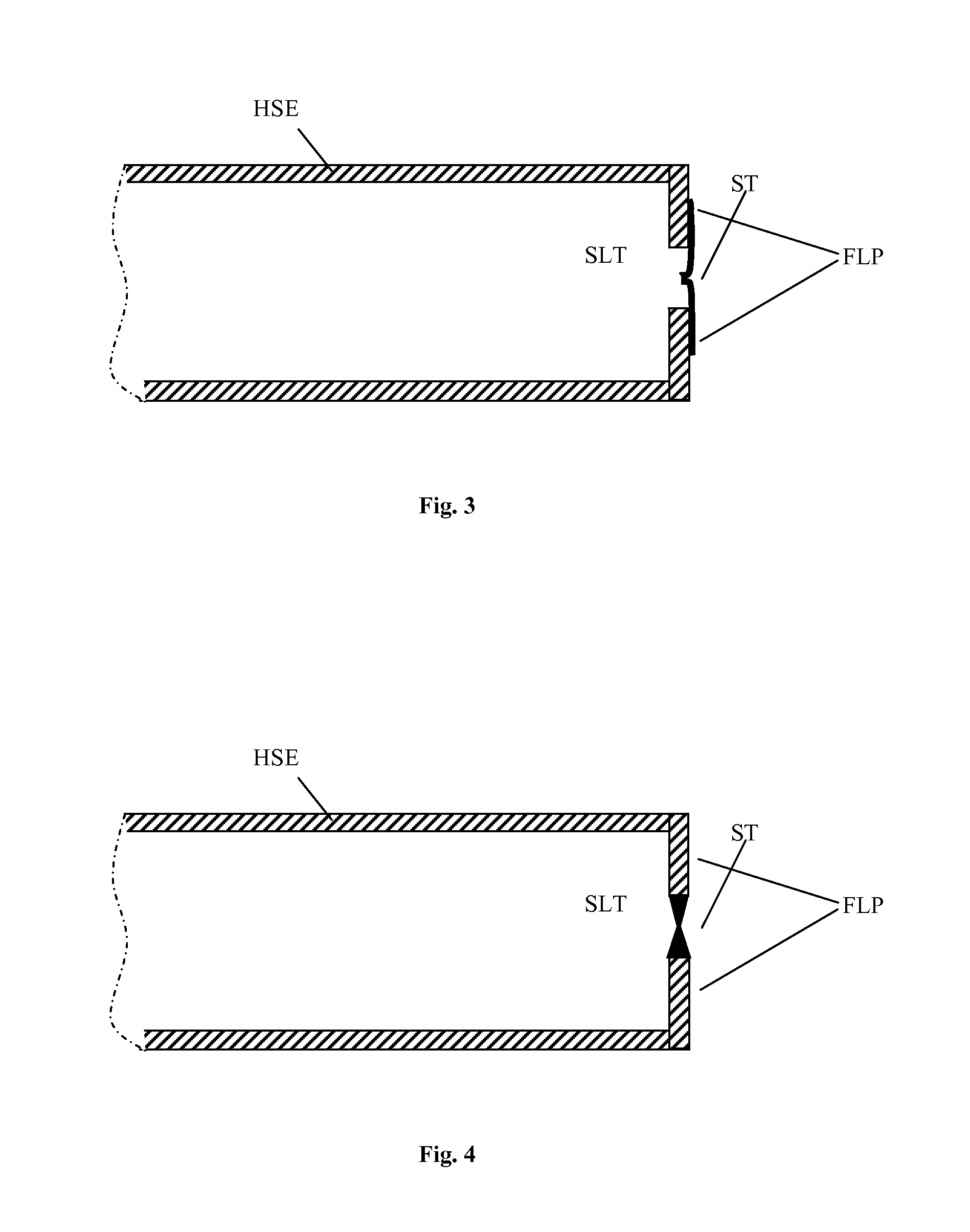
The present invention may be deployed in a system comprising a security module housed on a chip card and a host device comprising a chip card reader. The host device is comprised in a housing with a slot for the chip card. The housing is shielded to reduce the amount of electromagnetic radiation generated by the security module and / or the host device from penetrating to the exterior of the housing. Similarly, the shielding is adapted to reduce the effects of electromagnetic radiation generated outside of the host device on the components within the housing. The slot is also shielded by a flap made of an electrically conductive epoxy material or an electrically conductive resin.

Description

CROSS REFERENCE TO RELATED APPLICATIONS[0001]This application claims priority under 35 U.S.C. Section 119 to U.S. Provisional Application No. 61 / 414,907, filed Nov. 18, 2010, the entire contents of which are hereby incorporated by reference herein.INTRODUCTION[0002]The present invention relates to the domain of radio frequency electromagnetic interference and more specifically to methods and devices for the reduction of such interference in electronic circuits.STATE OF THE ART[0003]With the increasing use of higher and higher signal frequencies in the operation of electronic circuits, the problems related to electromagnetic interference or EMI are becoming more acute. In the domain of conditional access, the use of a security module is commonplace. A security module is usually used in cooperation with a host device which comprises at least a card reader to interface with the security module. The host device may further comprise a cryptographic module and other related conditional ac...

Claims


Application Information

Patent Timeline
Patent Type & Authority Patents(United States)
IPC IPC(8): H05K7/00H05K9/00G06F1/18
CPCH05K9/0018G06F1/182
Inventor OSEN, KARLODOOM, ERNEST
Owner NAGRAVISION SA
Learn More