Window hardware anchor

a hardware anchor and window frame technology, applied in the direction of threaded fasteners, nuts, mechanical devices, etc., can solve the problems of less advantageous vinyl or composite window sashes, weight and material cost, and inconvenient installation of windows, etc., to prevent lock rotation and anchor overexpansion, structural stability, and shorten the longitudinal length of the anchor

Active Publication Date: 2015-06-16
LAWRENCE BARRY G
View PDF13 Cites 6 Cited by
  • Summary
  • Abstract
  • Description
  • Claims
  • Application Information

AI Technical Summary

Benefits of technology

[0014]The aforesaid and other objectives are realized by providing a window hardware anchor defining a central channel connected to a plurality of spreadable projections forming a head. The anchor is snapably inserted into an aperture formed in the top surface of a sash and is releasably held in place by a pair of shoulders formed on the anchor exterior surface. A window lock defining a receiver on a bottom surface is positioned above the anchor and threaded fasteners such as screws are inserted through the lock housing and received within the central channel. As the fastener is tightened, the anchor head is widened as it receives the wider diameter fastener, mechanically urging the projections and the shoulders to displace laterally as the fastener augers, until the projections contact the receiver side walls and the shoulders contact the underside of the sash, preventing lock rotation and anchor overexpansion. The resulting attachment is structurally more stable than the prior art due to the increased surface area contacting the projections and limits torsional displacement by the lock housing and fastener due to the receiver contacting the anchor projections in addition to the shortened longitudinal length of the anchor due to the augered fastener.

Problems solved by technology

This method works well with wooden window sashes but is less advantageous for vinyl or composite window sashes that typically include an extruded frame with a hollow interior to reduce weight and material cost.
Fasteners do not hold well in such windows, leading to installed hardware that twists or slides during use.
This is a particularly egregious problem with the twisting or sliding leading to misalignment between locks or latches and associated keepers, resulting in windows that are not properly secured.
This increases the number of window components, assembly steps, and window cost.
By expanding from the bottom of the anchor, this option offers little in the way of a solution to the problem above.
Further, by driving the fasteners from above, the resulting hardware displays unsightly and aesthetically unpleasing screws and the like.

Method used


Image

  • Window hardware anchor
  • Window hardware anchor
  • Window hardware anchor

Examples


Embodiment Construction

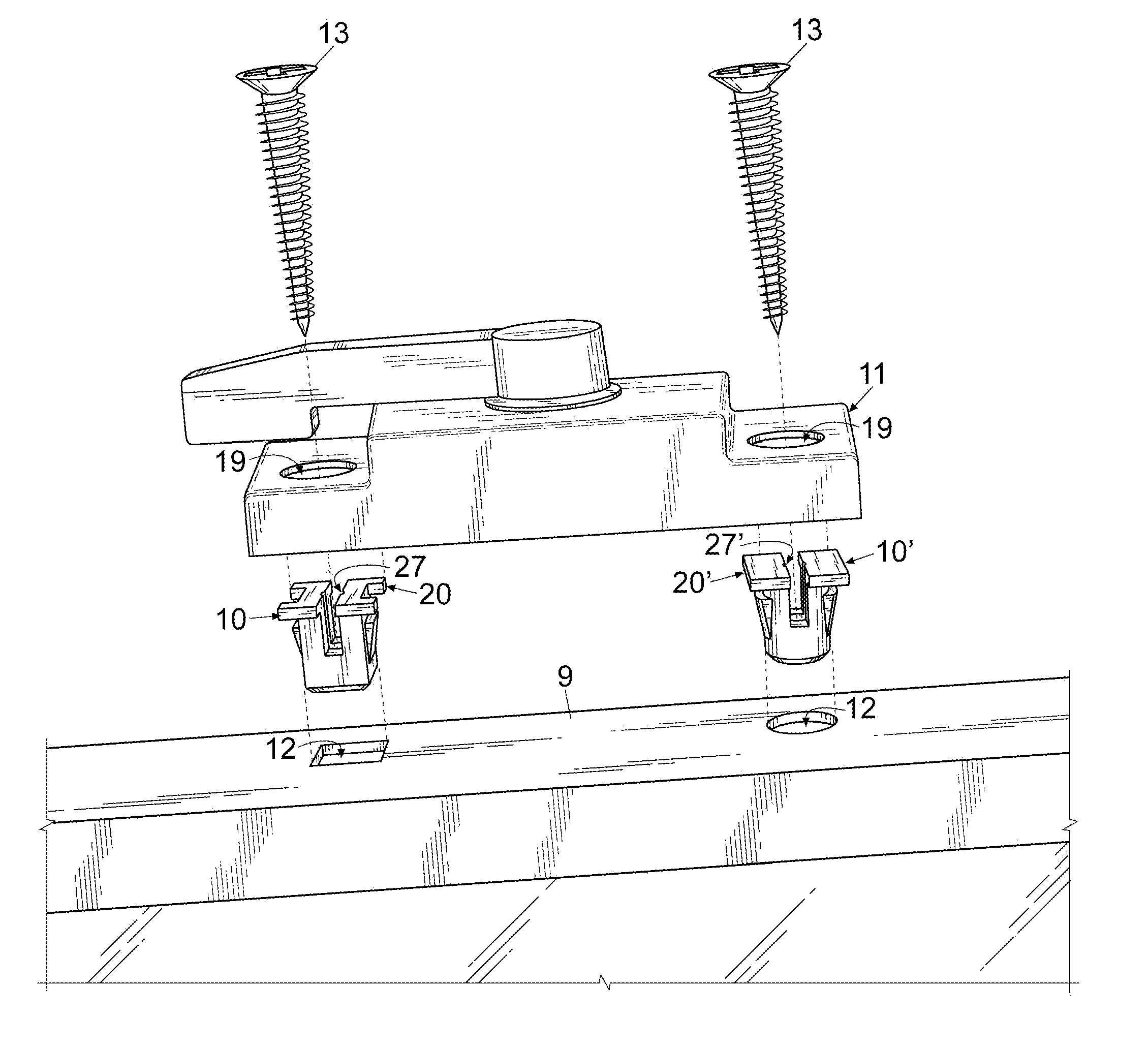
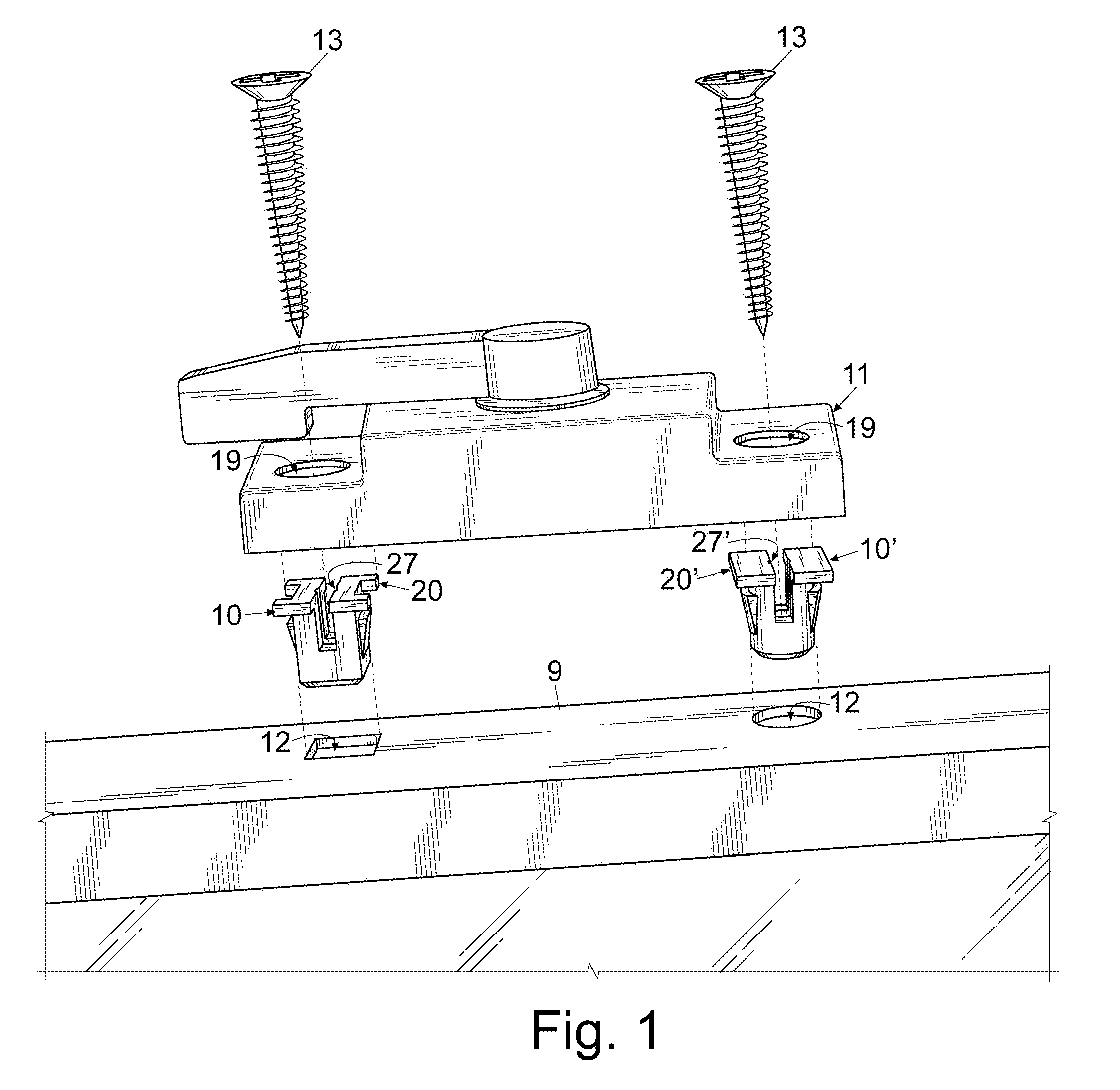
[0021]For a better understanding of the invention and its operation, turning now to the drawings, FIG. 1 shows an exploded side perspective view of window sash 9, hardware anchors 10, 10′, lock 11 and fasteners 13. Sash 9 defines one or more apertures 12 in the top surface sized to receive anchors 10, 10′. Although only two apertures 12 are represented in FIG. 1, it should be understood that any number of apertures 12 could be formed in sash 9 to correspond with the desired number of anchors 10, 10′, for example if additional anchors 10, 10′ were needed to secure a particularly unstable window lock 11 or associated keeper (not shown). Window lock 11 is shown in FIGS. 1 and 4 as the window hardware to engage anchors 10, 10′ via fasteners 13 and to be secured to sash 9, although it should be recognized that any window hardware fastened atop window sash 9 such as other lock styles, latches, keepers, and the like may also enjoy the benefits of anchors 10, 10′.

[0022]Hardware anchors 10, ...


PUM


Abstract

A window hardware anchor formed from a base and a pair of walls defining a central channel therebetween. The walls each form a spreadable projection at the end opposing the base and combine to define an anchor head. A pair of shoulders are attached in opposing relation on the outside of different walls, such that when a fastener is received in the central channel, the head and the shoulders laterally displace to form a stable attachment platform for desired window hardware.

Description

FIELD OF THE INVENTION[0001]The invention herein pertains to window hardware and particularly pertains to insertable window hardware anchors positioned within the hollow extrusion of a moveable window sash for securing window latches and locks thereto.DESCRIPTION OF THE PRIOR ART AND OBJECTIVES OF THE INVENTION[0002]Single and double hung windows have gained popularity recently due to their ease of manufacturing, installation, use, and cleaning. Sash locks and latches are often mounted to a sash rail by fasteners such as screws that are driven through the hardware body and engage the material of the sash rail. Depending on the window material, holes may be drilled prior to installation once the hardware position is determined. This method works well with wooden window sashes but is less advantageous for vinyl or composite window sashes that typically include an extruded frame with a hollow interior to reduce weight and material cost. Fasteners do not hold well in such windows, leadi...

Claims


Application Information

Patent Timeline
Patent Type & Authority Patents(United States)
IPC IPC(8): F16B37/04F16B5/02
CPCF16B5/02E05B9/08E05B65/087E05C3/044F16B13/0833F16B21/086
Inventor LAWRENCE, BARRY G.
Owner LAWRENCE BARRY G
Why Eureka
Try Eureka