Deskew apparatus and method for peripheral component interconnect express

a peripheral component and interconnect technology, applied in the direction of synchronisation signal speed/phase control, recording signal processing, instruments, etc., can solve the problems of byte skew not being compensated, width and operating speed,

Inactive Publication Date: 2015-06-16
ELECTRONICS & TELECOMM RES INST
View PDF26 Cites 3 Cited by
  • Summary
  • Abstract
  • Description
  • Claims
  • Application Information

AI Technical Summary

Benefits of technology

[0011]Accordingly, the present invention has been made keeping in mind the above problems occurring in the prior art, and an object of the present invention is to provide a deskew apparatus and method for PCI Express, which is a technology for removing the skew between lanes without loss of data in the physical layer of PCI Express including multiple lanes, and which can align input data, composed of two upper and lower bytes, that is, 16 bits, rather than 1 byte, that is, 8 bits (i.e., the basic unit of data in the PCI Express standard), based on the lower byte, thereby preventing data from being lost.
[0012]Another object of the present invention is to provide a deskew apparatus and method for PCI Express, which can detect a change in a state of alignment attributable to the deletion or addition of an SKP symbol when data is aligned, thus being able to deal with data being in a state of non-alignment as occurs because of the use of an SKP sequence set that compensates for the difference in the clock speed between lanes.

Problems solved by technology

In the recent 5 Gbp scheme, however, the data width and operating speed of the interface are typically 16 bits and 250 MHz because of the limitations of a protocol engine.
However, it is problematic in that a byte skew is not compensated for when an SKP symbol is transmitted after a COM symbol and the SKP symbol is added or deleted.

Method used


Image

  • Deskew apparatus and method for peripheral component interconnect express
  • Deskew apparatus and method for peripheral component interconnect express
  • Deskew apparatus and method for peripheral component interconnect express

Examples


Embodiment Construction

[0047]The embodiments of the present invention will be described with reference to the accompanying drawings in order to fully describe the present invention so that persons having ordinary skill in the art can easily practice the technical spirit of the present invention. It should be noted that similar reference symbols are used to designate similar elements throughout the drawings even when the elements are depicted in different drawings. Furthermore, in the following description of the present invention, detailed descriptions of one or more related well-known constructions and / or one or more functions which have been deemed to make the gist of the present invention unnecessarily vague will be omitted.

[0048]A deskew apparatus and method for PCI Express according to embodiments of the present invention will be described in detail with reference to the accompanying drawings.

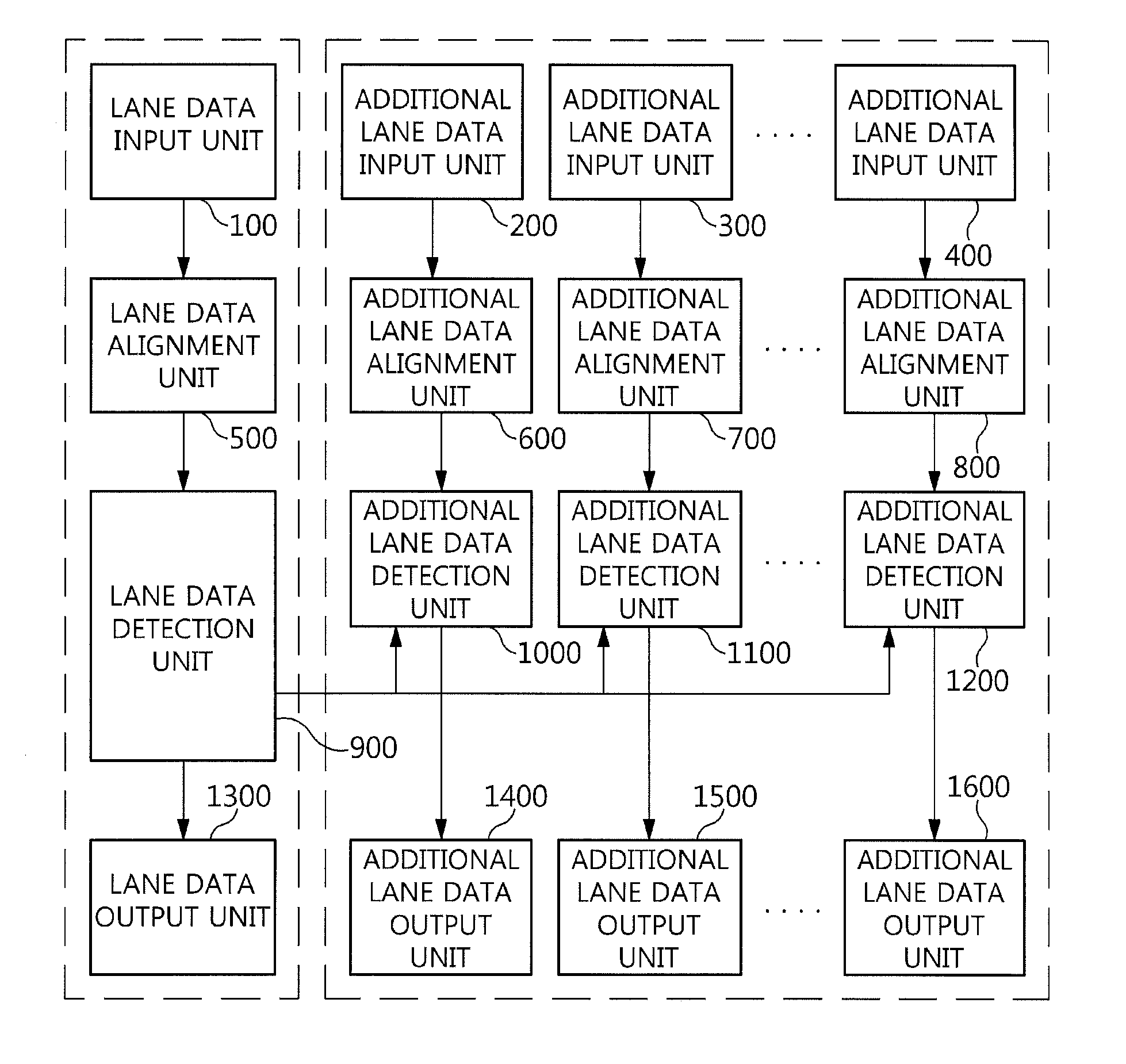
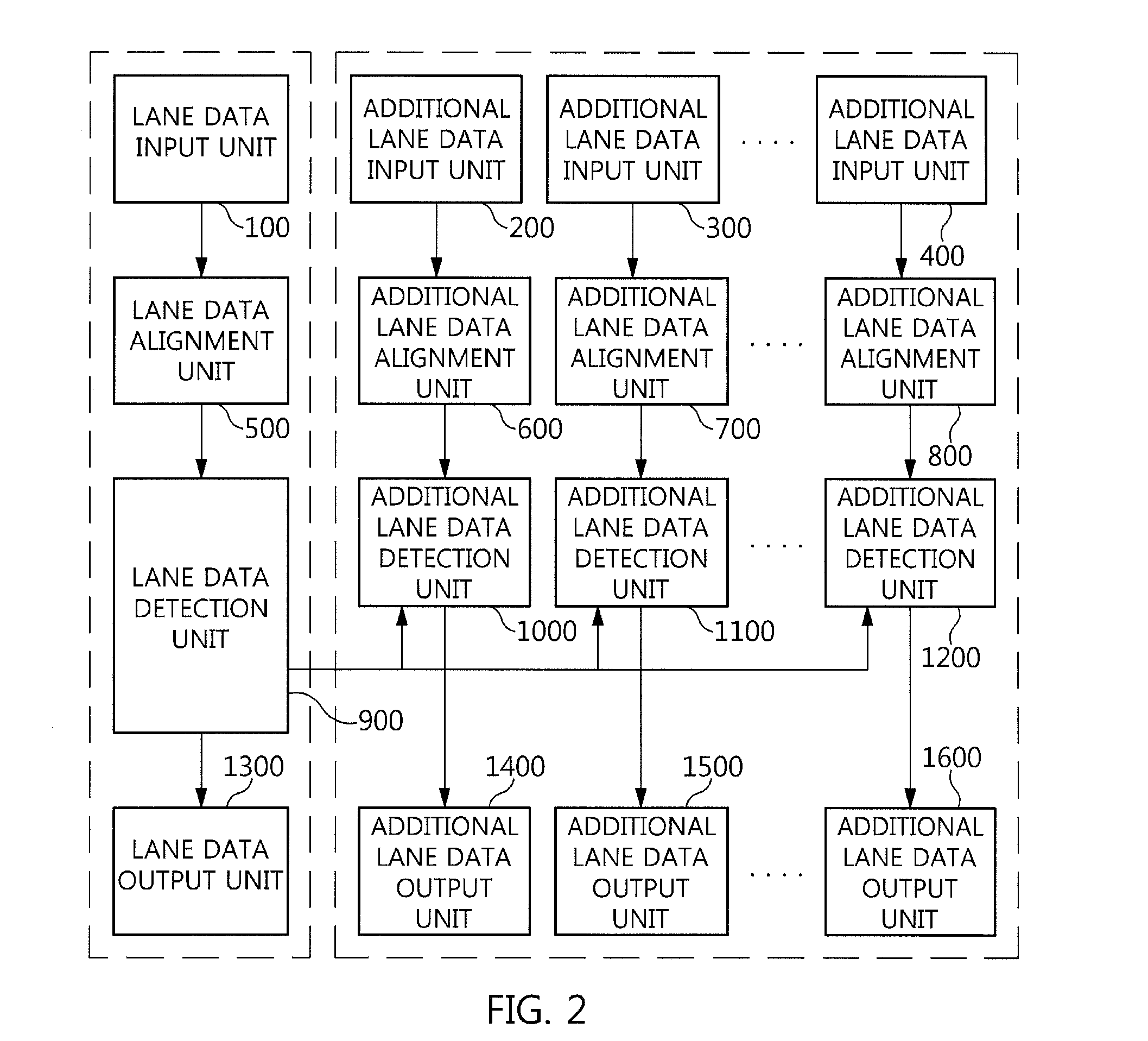
[0049]FIG. 2 shows the configuration of a deskew apparatus for PCI Express according to an embodiment of the ...


PUM


Abstract

Disclosed herein are a deskew apparatus and method for Peripheral Component Interconnect (PCI) Express for compensating for a skew. The deskew apparatus includes a lane data input unit, a lane data alignment unit, and a lane data detection unit. The lane data input unit receives 18-bit data from each of lanes of the PCI Express. The lane data alignment unit aligns the 18-bit data using a COM symbol. The lane data detection unit detects a change in a state of alignment of the 18-bit data attributable to deletion or addition of an SKP symbol when the 18-bit data is aligned, and to perform synchronization between the lanes.

Description

CROSS REFERENCE TO RELATED APPLICATION[0001]This application claims the benefit of Korean Patent Application No. 10-2012-0035725, filed on Apr. 5, 2012, which is hereby incorporated by reference in its entirety into this application.BACKGROUND OF THE INVENTION[0002]1. Technical Field[0003]The present invention relates generally to a deskew apparatus and method for Peripheral Component Interconnect (PCI) Express and, more particularly, to a deskew apparatus and method for PCI Express which align input data in PCI Express on an 18-bit basis, thereby compensating for static skew as well as dynamic skew.[0004]2. Description of the Related Art[0005]The speed of PCI Express was typically 2.5 Gbps in its early stage, and is now 5 Gbps in line with the trend of favoring high speed. An 8-Gbp device is expected to be released in the near future. The unit of data that is basically used in PCI Express is 1 byte, that is, 8 bits. In the early 2.5 Gbp scheme, the data width and operating speed of...

Claims


Application Information

Patent Timeline
Patent Type & Authority Patents(United States)
IPC IPC(8): G06F11/07G06F13/10G06F5/06G06F13/40H04J3/06H04L7/00G06F13/38G06F13/42H04L7/10H04J3/07
CPCG06F11/0793G06F13/102G06F13/385G06F5/06G06F13/4013G06F13/4217G06F13/42G06F13/4027H04J3/062H04L7/005H04L7/10G06F13/4278H04J3/073H04J3/0629G06F13/423G06F13/00
Inventor CHOI, YONG-SEOK
Owner ELECTRONICS & TELECOMM RES INST
Why Eureka
Try Eureka