
Printer

a printing machine and printing plate technology, applied in printing machines, typewriters, etc., can solve the problems of reducing the density of the code image, reducing the density of the image, and increasing the size of the dots, so as to suppress the degradation of readability and suppress the bleeding of recording materials or the like due to the increase in the amount of recording materials applied

Active Publication Date: 2015-06-23
RISO KAGAKU CORP
View PDF5 Cites 4 Cited by
  • Summary
  • Abstract
  • Description
  • Claims
  • Application Information

AI Technical Summary

Benefits of technology

[0011]The lower the print resolution, the larger the spaces produced between the dots decreased in size. For this reason, even when the dots forming a code image are decreased in size, a printer having high print resolution can reduce the areas of the spaces produced between the dots, and consequently can alleviate decrease in the density of the code image.
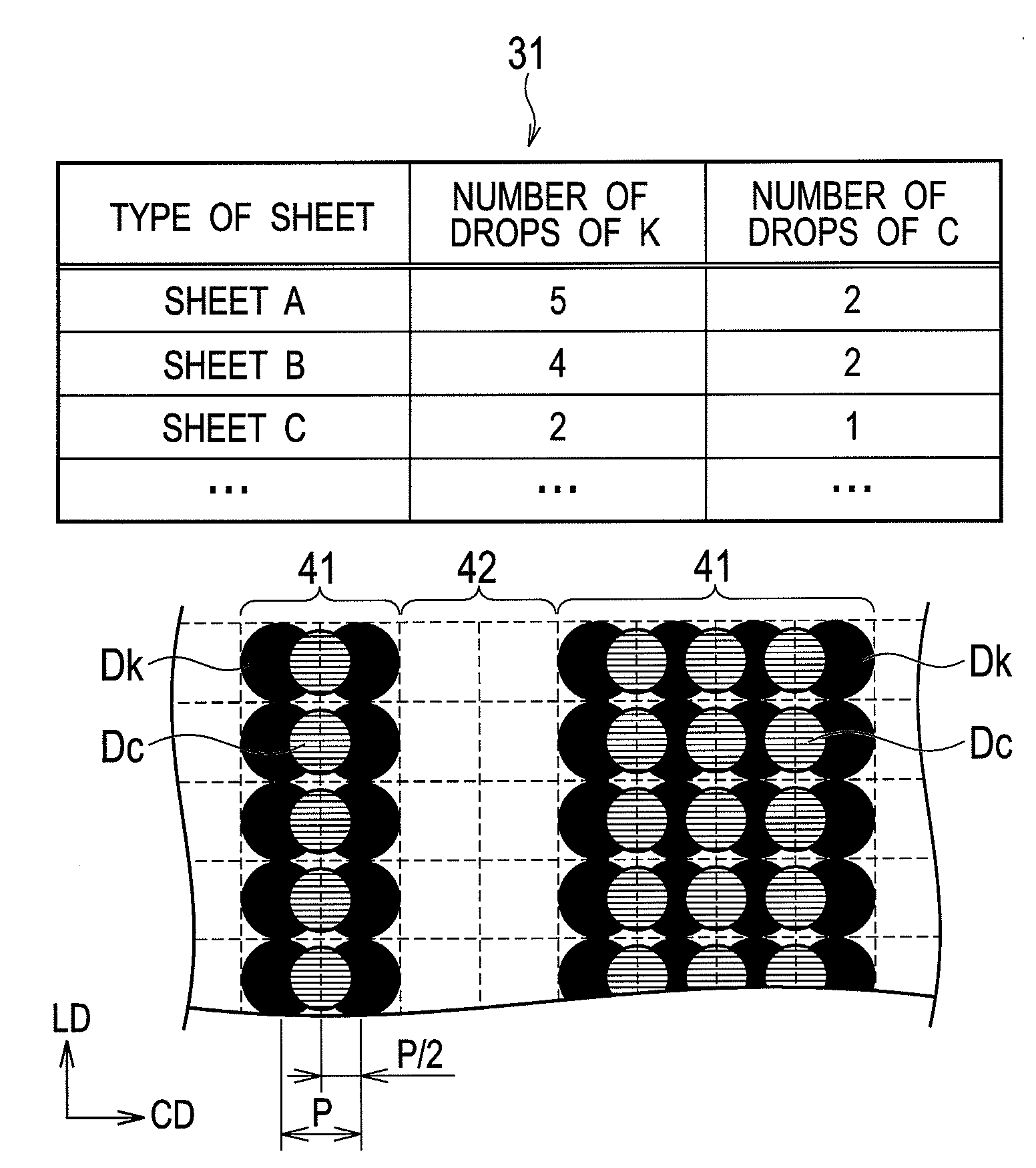
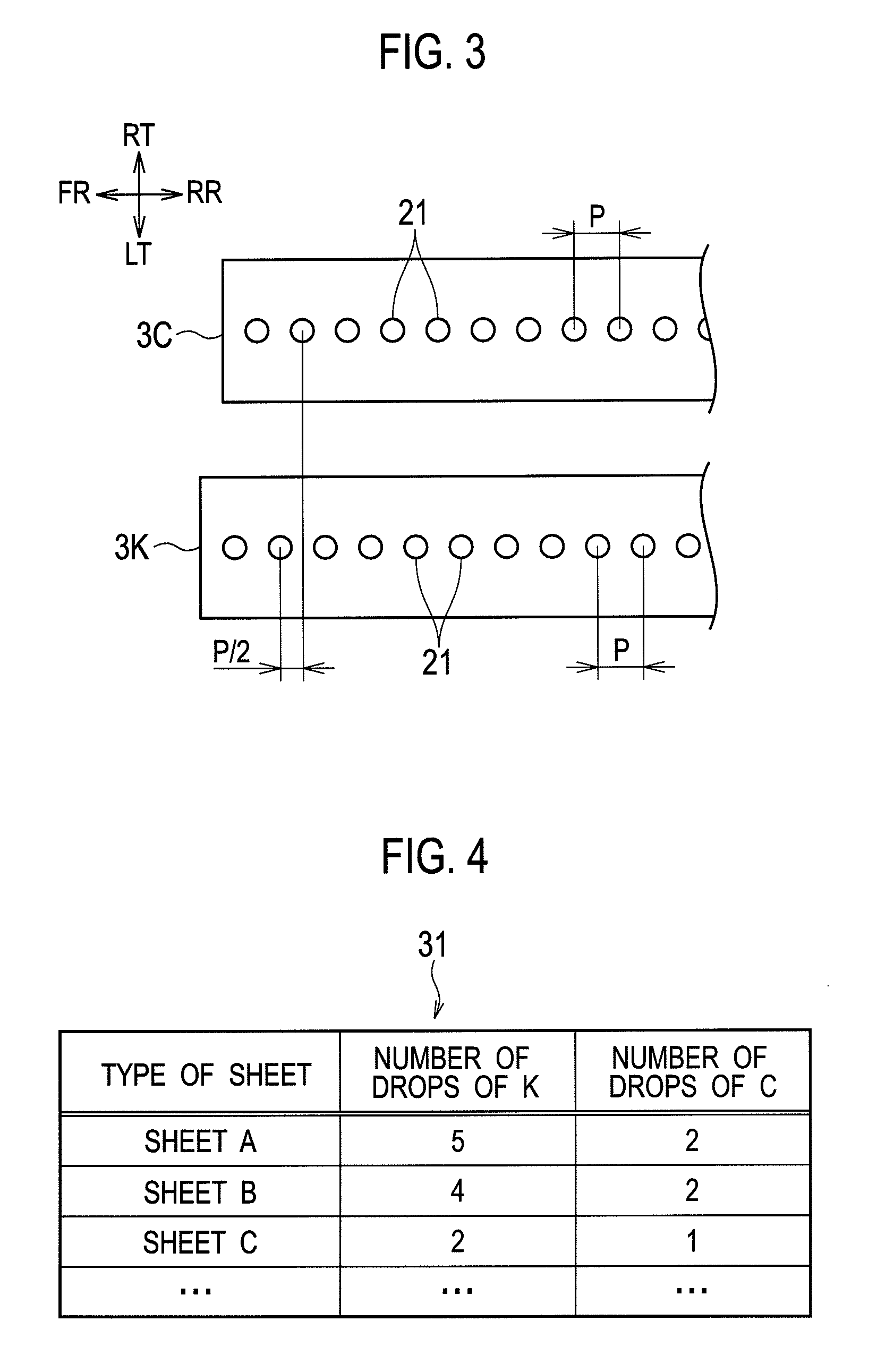
[0017]According to the above configuration, in printing a code image, in a region with a width of two or more pixels having first dots formed by a first printing unit, a second printing unit forms second dots between the first dots in a width direction of the region. Thereby, a code image in which degradation in readability is suppressed can be printed without requiring sophisticated printing units capable of high resolution printing or the like.

Problems solved by technology

In printing such as inkjet printing which forms an image on a print medium by use of dots, the dots tend to increase in their size due to, for example, bleeding of ink.
When the barcode is printed on a sheet on which ink easily bleeds, the above-mentioned problem of the degradation in the barcode readability occurs more likely.
However, when the dots forming a code image are decreased in size, spaces are produced between the dots, lowering the density of the code image.
As a result, for example, when the density of black bars in a barcode is low, the contrast between the bars and white spaces is low, which leads to the degradation in the barcode readability by a reader.
However, high-resolution printing requires a sophisticated printing unit.
In the case of decreasing the size of only the dots in the edge portion of a print region, it is not easy to print the black bars in a barcode, for example, exactly with their desired widths unless the size of the dots can be controlled with high accuracy.
In particular, when the code image is printed on a sheet with ink, such as oil-based ink, which is very likely to bleed on a sheet, it is difficult to control the size of the dots as desired.

Method used


Image

  • Printer
  • Printer
  • Printer

Examples


Embodiment Construction

[0034]With reference to the drawings, an embodiment of the present invention is described below. Throughout the drawings, the same or like portions or elements are denoted by the same or like reference numerals. In addition, it should be noted that the drawings are only schematic and ratios of dimensions and the like are different from actual ones. Moreover, the drawings naturally include portions having different dimensional relationships and ratios from each other.

[0035]The embodiment is given below only to provide an example of a machine and the like for embodying a technical concept of the present invention, and the technical concept of the present invention does not limit the arrangement of elements and the like to what is described below. The technical concept of the present invention can be variously changed without departing from the scope of claims.

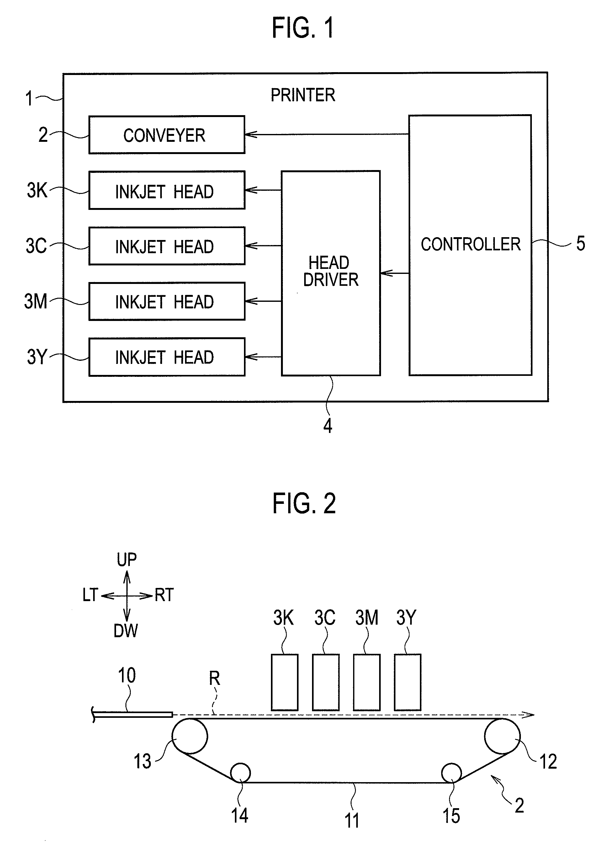
[0036]FIG. 1 is a block diagram showing the configuration of a printer according to the embodiment of the present invention. FI...


PUM


Abstract

A printer includes a first printing unit configured in printing a code image to form first dots on respective pixels of the code image and a second printing unit configured in printing the code image to form second dots between the first dots in a width direction of a region with a width of two or more pixels having the first dots formed by the first printing unit.

Description

CROSS REFERENCE TO RELATED APPLICATION[0001]This application is based upon and claims the benefit of priority from the prior Japanese Patent Application No. 2012-149441, filed on Jul. 3, 2012, the entire contents of which are incorporated herein by reference.BACKGROUND[0002]1. Technical Field[0003]The present invention relates to a printer configured to print on a print medium.[0004]2. Related Art[0005]Information codes are known, such as a barcode or a two-dimensional code typified by a QR code (registered trademark). In view of high-mix, small-lot production, on-demand printing is drawing attention for printing an image of an information code (a code image) on paper or the like. In particular, a line inkjet head printer, with which high-speed printing is easy, is expected to be used to print a code image.[0006]An information code represents information by, for example, the widths of bars or the arrangement of cells that constitute the code. Hence, if the widths of the bars in a pr...

Claims


Application Information

Patent Timeline
Patent Type & Authority Patents(United States)
IPC IPC(8): B41J2/165B41J2/21B41J2/135B41J3/01
CPCB41J2/135B41J2/2132B41J3/01
Inventor SHIMOMURA, KENJIHAYASHI, HIROSHI
Owner RISO KAGAKU CORP
Learn More