Vehicle control device and vehicle control method

a technology of vehicle control and control device, which is applied in the direction of braking system, braking components, transportation and packaging, etc., can solve the problems of large variations in vehicle drive force and create an unnatural feeling for the driver, and achieve the effect of reducing the level of unnatural feeling experienced by the driver and minimizing the variation in drive for

Active Publication Date: 2015-06-23
NISSAN MOTOR CO LTD
View PDF8 Cites 22 Cited by
  • Summary
  • Abstract
  • Description
  • Claims
  • Application Information

AI Technical Summary

Benefits of technology

[0007]An object of the present invention is to provide a vehicle control device and vehicle control method capable of reducing unnatural feel experienced by a driver.
[0009]As a result, vehicle body orientation is not controlled using drive force from a motive power source when amplitude is high, allowing variations in drive force to be minimized and the level of unnatural feel experienced by a driver to be reduced.

Problems solved by technology

However, a problem exists that controlling vehicle body orientation using drive force from a motive power source when a state quantity indicating vehicle body orientation has a high amplitude will lead to large variations in vehicle drive force, creating an unnatural feel for the driver.

Method used


Image

  • Vehicle control device and vehicle control method
  • Vehicle control device and vehicle control method
  • Vehicle control device and vehicle control method

Examples


first embodiment

[0035](First Embodiment)

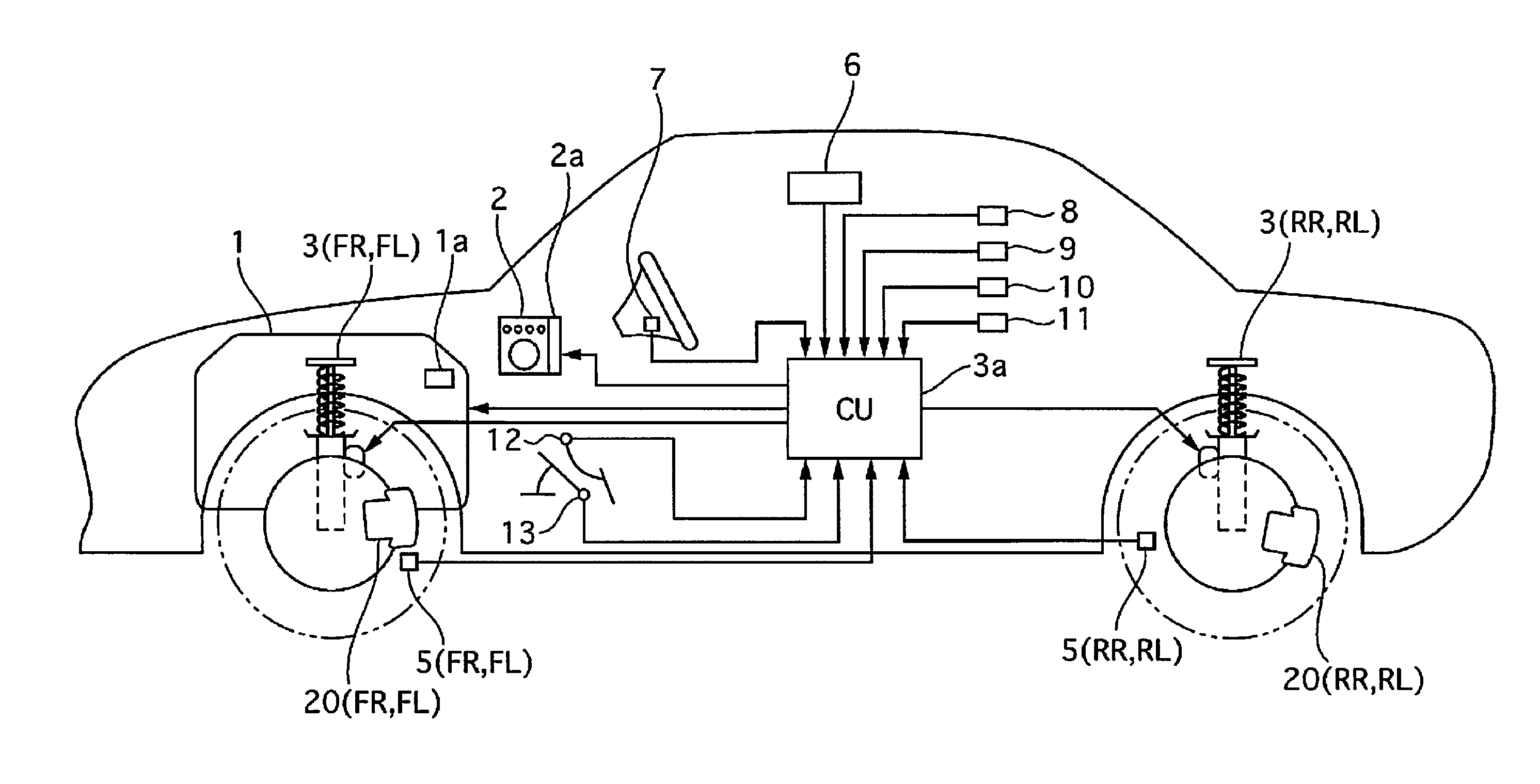
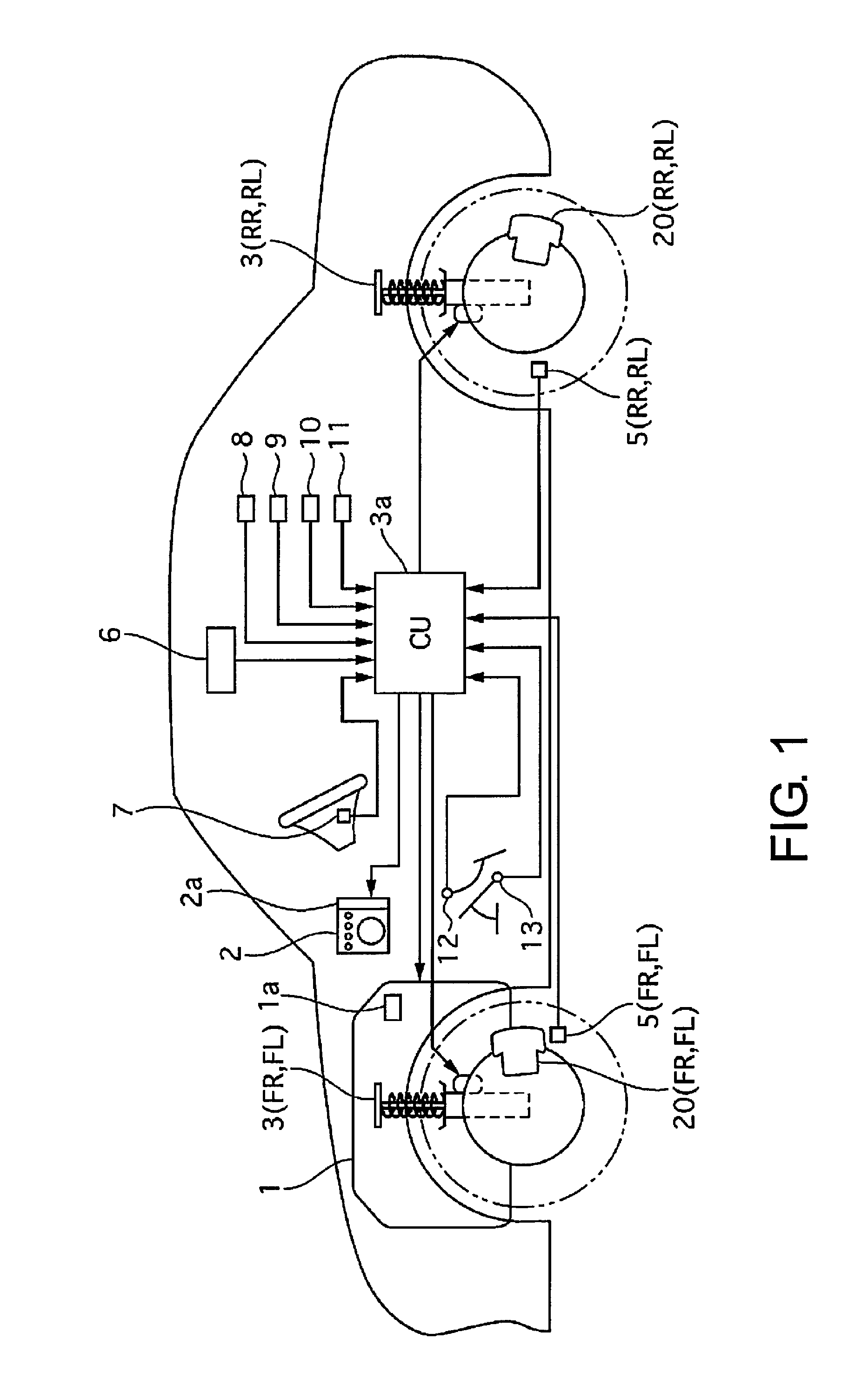
[0036]FIG. 1 is a schematic system diagram of a vehicle control device according to a first embodiment. A vehicle comprises an engine 1 constituting a power source, brakes 20 for generating braking torque by applying frictional force to the wheels (brakes corresponding to individual wheels will be referred to hereafter as follows: front right brake: 20FR; front left brake: 20FL; rear right brake: 20RR; rear left brake: 20RL), and variable-damping-force shock absorbers 3 provided between each of the wheels and the vehicle body (“shock absorber” will be abbreviated “S / A” in the following description; shock absorbers corresponding to individual wheels will be referred to as follows: front right S / A: 3FR; front left S / A: 3FL; rear right S / A: 3RR; rear left S / A: 3RL).

[0037]The engine 1 comprises an engine controller 1a (also referred to hereafter as an engine control unit) for controlling the torque outputted by the engine 1; the engine controller 1a controls the ...

second embodiment

[0211](Second Embodiment)

[0212]FIG. 24 is a control block diagram of actuator control amount calculation processes performed during pitch control in a second embodiment. The second embodiment differs from the first embodiment in that the operation switching unit 337 switches the operation of the actuators on and off on the basis of the roll rate instead of the pitch rate.

[0213]In the second embodiment, the action of the operation switching unit 337 causes pitch control to be performed using the engine torque control amount alone when the absolute value of the amplitude of the roll rate is less than a first predetermined value, using the damping force control amount instead of the engine torque control amount when the absolute value of the amplitude of the roll rate is equal to or greater than the first predetermined value and less than the second predetermined value, and using the braking torque control amount instead of the damping force control amount when the absolute value of th...


PUM


Abstract

A driving state estimator unit configured to detect a state quantity indicating vehicle body orientation, and a control unit configured to control vehicle body orientation using drive force from an engine when the absolute value of the amplitude of the detected state quantity is less than a second predetermined value, and using force generated by a second orientation control device instead of the drive force from the engine when the absolute value of the amplitude is equal to or greater than the second predetermined value.

Description

CROSS-REFERENCE TO RELATED APPLICATIONS[0001]This application is a U.S. National stage application of International Application No. PCT / JP2013 / 051171, filed Jan. 22, 2013, which claims priority to Japanese Patent Application No. 2012-012593 filed in Japan on Jan. 25, 2012, Japanese Patent Application No. 2012-012594 filed in Japan on Jan. 25, 2012, and Japanese Patent Application No. 2012-012595 filed in Japan on Jan. 25, 2012, the contents of each of which are hereby incorporated herein by reference.BACKGROUND[0002]1. Field of the Invention[0003]The present invention relates to a control device and a control method for controlling the state of a vehicle.[0004]2. Background Information[0005]Japanese Laid-Open Patent Application No. 2009-247157 discloses a technique of controlling vehicle body orientation using drive force from a motive power source.SUMMARY[0006]However, a problem exists that controlling vehicle body orientation using drive force from a motive power source when a sta...

Claims


Application Information

Patent Timeline
Patent Type & Authority Patents(United States)
IPC IPC(8): B60G17/018B60W10/06B60W10/184B60T8/1755B60G17/0165B60T13/66B60G17/016B60G17/0195B60T7/12B60W30/20B60W10/22B60G17/06
CPCB60T7/12B60W10/22B60W30/20B60G17/016B60T13/662B60W10/06B60W10/184B60T8/17555B60G17/0165B60G17/0195B60G17/06B60W2710/182B60W2710/223B60W2710/226B60G2500/10B60W2030/206B60W2520/16B60W2710/0666B60T2260/06B60G2400/821B60G2400/91
Inventor KIKUCHI, HIRONOBUHIRAYAMA, KATSUHIKO
Owner NISSAN MOTOR CO LTD
Why Eureka
Try Eureka