Imaging apparatus, control method, and non-transitory storage medium

Active Publication Date: 2018-10-04
CANON KK
View PDF3 Cites 5 Cited by
  • Summary
  • Abstract
  • Description
  • Claims
  • Application Information

AI Technical Summary

Benefits of technology

[0005]The present invention provides a technology for reducing an unnatural feeling given to a user when di

Problems solved by technology

If a difference in image quality between images occurs due to reasons as described above, images having different brightness, resolution, contrast, and the like are alternately displayed, and thus an unnatur

Method used


Image

  • Imaging apparatus, control method, and non-transitory storage medium
  • Imaging apparatus, control method, and non-transitory storage medium
  • Imaging apparatus, control method, and non-transitory storage medium

Examples


first embodiment

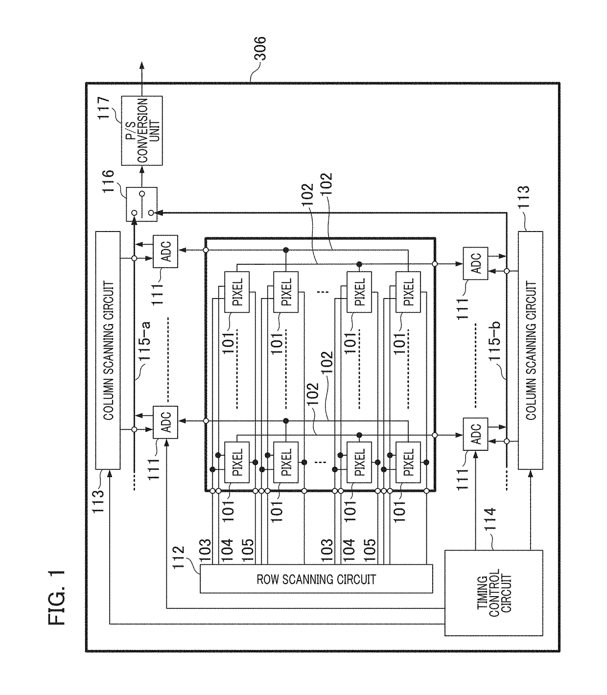
[0032]FIG. 1 is a schematic block diagram which shows a configuration example of an imaging element in a first embodiment of the present invention. An imaging element 306 has a configuration in which a large number of pixel portions 101 are arranged in a two-dimensional array shape. Each of a vertical output line 102, a transfer signal line 103, a reset signal line 104, and a row selection signal line 105 is connected to each of the pixel portions 101. A column ADC block 111 outputs a signal obtained by performing an analog to digital (A / D) conversion on a signal output from the vertical output line 102 connected to the pixel portion 101. A row scanning circuit 112 is connected to the pixel portion 101 by the transfer signal line 103, the reset signal line 104, and the row selection signal line 105. A plurality of column scanning circuits 113 are connected to a plurality of column ADC blocks 111 by horizontal signal lines 115-a and 115-b. A timing control circuit 114 outputs a timin...

second embodiment

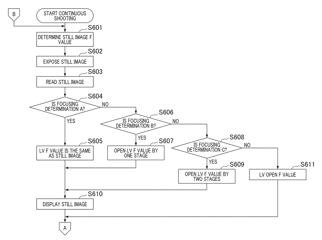
[0071]Next, a second embodiment of the present invention will be described. In the present embodiment, a configuration in which the aperture at the time of live view photographing is controlled in accordance with a difference in focal distance of the lens unit 301 or object distance, in addition to the aperture state at the time of still image photographing, will be described. In the present embodiment, the same reference numerals which have been already used will be used for the same constituents as in the first embodiment, so that the descriptions thereof will be omitted and differences will be mainly described.

[0072]The appearance of an image varies greatly if the aperture value changes according to a difference in focal distance of the lens unit 301. For example, if the aperture value is changed by two stages with a short focal distance at a wide angle, a change in appearance of an image is small, but if the aperture value is changed by two stages at the time of telephoto with a...

third embodiment

[0090]FIG. 11 is a block diagram which shows a configuration of an imaging apparatus having the form of a camera system made of a camera main body capable of interchanging a plurality of photographing lens and a photographing lens according to a third embodiment of the present invention. The camera system (the imaging apparatus) of the present embodiment is a lens interchangeable single lens reflex camera, and includes a lens unit 1100 made of a photographing lens and the camera main body 1120. The lens unit 1100 is attached to the camera main body 1120 via the mount M indicated by a dotted line in the center of FIG. 11.

[0091]The lens unit 1100 includes an imaging optical system (a first lens group 1101, an aperture 1102, a second lens group 1103, and a third lens group (a focus lens 1104)), a drive and control system. The first lens group 1101 is disposed at the tip of the lens unit 1100 and is movably held in an optical axis direction OA. The aperture 1102 has a function as a mech...


PUM


Abstract

According to an aspect of the invention, an imaging apparatus includes a first control unit configured to control exposure parameters of an imaging element, and a second control unit configured to perform processing of switching between and outputting a first image corresponding to pixel portions of a number of first pixels and a second image corresponding to pixel portions of a number of second pixels smaller than the number of first pixels among pixel portions of the imaging element. The second control unit performs focusing determination on the basis of at least one of the first image and the second image.

Description

BACKGROUND OF THE INVENTIONField of the Invention[0001]The present invention relates to an imaging apparatus, a control method, and a storage medium.Description of the Related Art[0002]Among imaging apparatuses such as digital cameras, there is an imaging apparatus having a continuous shooting (continuous photographing) function of performing continuous still image photographing while performing automatic focus detection (imaging plane phase difference AF) with an imaging plane phase difference method on a main object. During execution of this continuous shooting function, the imaging apparatus reads each of images to be displayed as live view (LV) images on a back monitor or the like and recorded images to be recorded as still images, and performs display and recording of the images in real time.[0003]For example, a technology for improving the followability with respect to a main object when an image acquired from the imaging element is displayed on a display device as a live view...

Claims


Application Information

Patent Timeline
IPC IPC(8): H04N5/232H04N5/235G03B13/36
CPCH04N5/23212H04N5/2353H04N5/23293G03B13/36H04N23/54H04N23/50H04N23/55H04N23/67H04N23/80H04N9/64H04N23/672H04N23/683H04N23/667H04N23/72H04N23/745H04N25/53H04N23/10H04N23/63H04N23/73
Inventor FURUMOCHI, HIROYUKITAMAKI, YOSHIHITOHAMANO, HIDEYUKI
Owner CANON KK
Why Eureka
Try Eureka