Method for operating an electromagnetic transfer system, and transfer system

a technology of electromagnetic transfer system and transfer system, which is applied in the direction of conveyor parts, mechanical conveyors, non-mechanical conveyors, etc., can solve the problem of not being able to deliver items, and achieve the effect of simple mechanical construction or design of transport elements

Active Publication Date: 2015-06-23
SYNTEGON TECHNOLOGY GMBH
View PDF23 Cites 19 Cited by
  • Summary
  • Abstract
  • Description
  • Claims
  • Application Information

AI Technical Summary

Benefits of technology

[0004]Based on the prior art described above, it is the aim of the invention to further develop a method for operating an electromagnetic transfer system in such a way that the items can be delivered by means of the transport elements to a downstream conveyor device such that said items can there be mutually spaced apart from one another at a distance which is less than the difference between the length of a transport element and that of the items. This aim is met by a method for operating an electromagnetic transfer system according to the invention. The concept underlying the invention is therefore to vary the feed rate of the downstream conveyor device or the conveyance speed of the transport element on the carrier path in the delivery area such that virtually an excess speed of the items results at the delivery point from the transfer system to the downstream conveyor device; thus enabling the items to be delivered to said downstream conveyor device spaced apart at a distance which is less than the length of the conveyor element in the direction of transportation.
[0006]In order to reduce the mechanical stresses on the transport element as well as in particular on the items, it is proposed in a particularly preferred variant of the method that the speed of the transport element be increased along a path section before the delivery region. It is therefore possible to continuously increase the speed of the conveyor element up until the delivery point; thus enabling a transport to occur in a product-protective manner.
[0009]A particularly simple mechanical construction or design of the transport elements is made possible if the delivery region of the items into the (downstream) conveyor device is situated in a curve entry region of the transport path. Due to the design of the transport path, the transport element can in this case be pivoted out of the further conveyance path of the item so that said transport element does not present an obstacle in particular to a successive item.

Problems solved by technology

Applications in which the items have a dimension in their direction of transportation in the transfer system that is significantly less than the overall length of the transport element can, however, present a problem.
Using the device disclosed by U.S. Pat. No. 6,876,107 B2 or the operating method thereof, it is therefore not possible to deliver items, which have a dimension or, respectively, length in the direction of transportation that is less than that of the transport element, to the downstream conveyor device so as to be spaced apart at a distance which is less than the difference between the length of the transport element and the items.

Method used


Image

  • Method for operating an electromagnetic transfer system, and transfer system
  • Method for operating an electromagnetic transfer system, and transfer system
  • Method for operating an electromagnetic transfer system, and transfer system

Examples


Embodiment Construction

[0015]Identical components or components having the same function are provided with the same reference numerals.

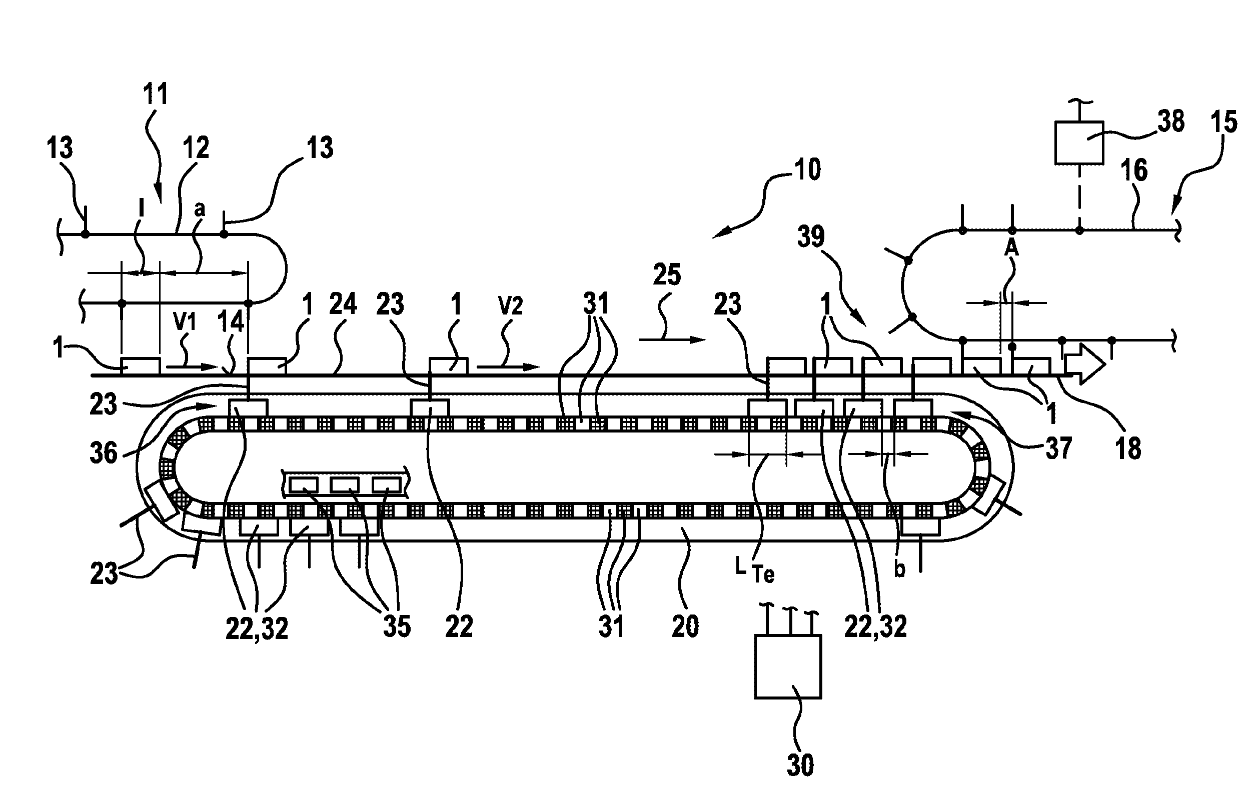
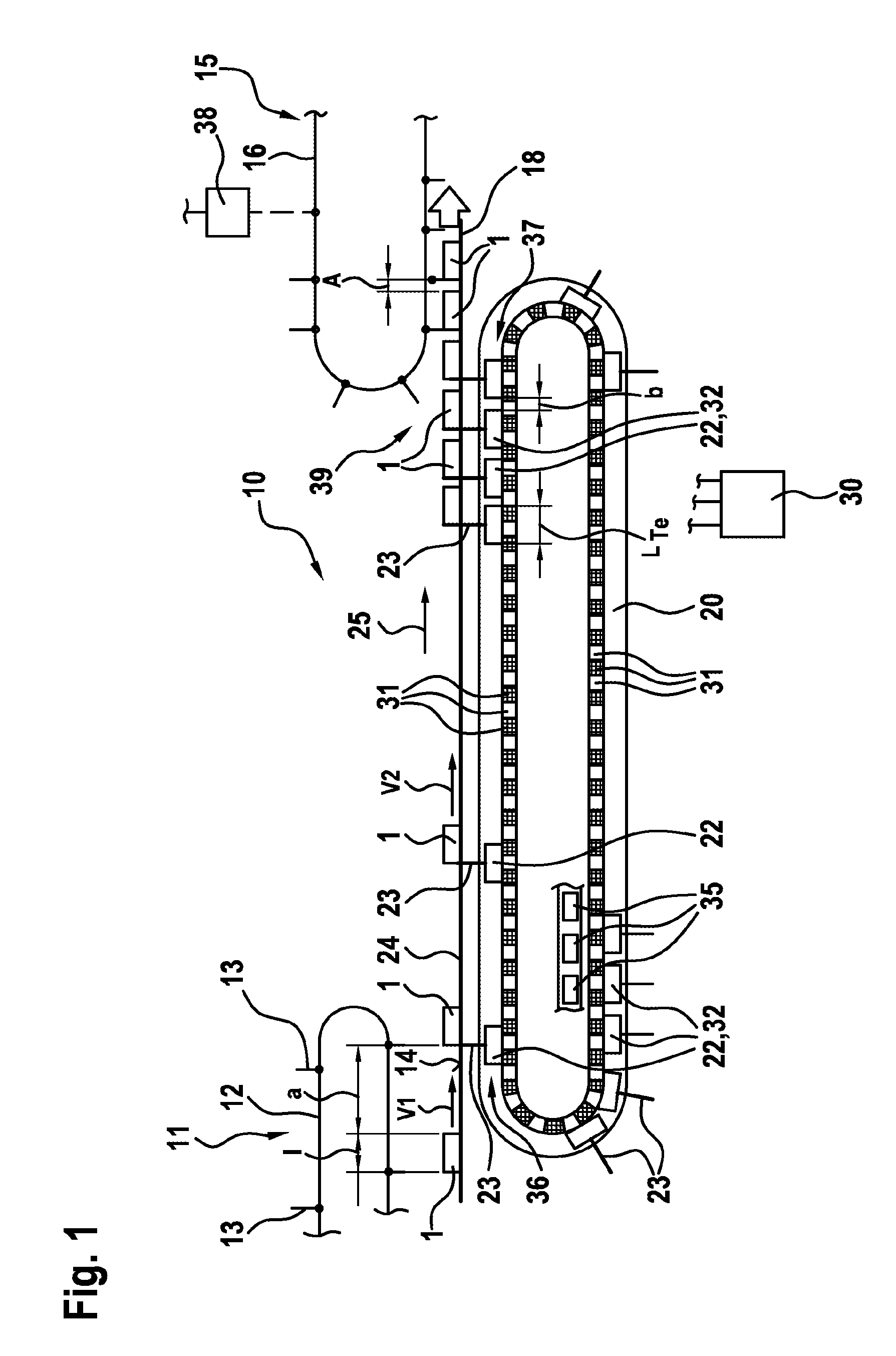
[0016]In FIG. 1, a transfer system 10 for conveying items 1 or, respectively, products is depicted. The items 1 are only symbolically depicted in the figures. Said items 1 can relate, for example, to packagings which, for example, are filled with chocolate bars, cookies or the like or else to other items which are to be packaged by means of a packaging machine located immediately downstream of the transfer system 10.

[0017]The items 1 are conveyed to the region of the transfer system 10 by means of a feeder device 11, which is not shown here in detail. The feeder device 11 can, for example, relate to a packaged goods chain conveyor 12 comprising driver elements 13 which are fastened to the packaged goods chain conveyor 12 at equal distances from one another. The spacing a between two items 1 in the region of the feeder device 11 results therefore from the difference in leng...


PUM


Abstract

The invention relates to a method for operating an electromagnetic transfer system (10) which is used to convey items (1; 1a) to a downstream conveyor device (15), and which comprises a carrier path (20), preferably designed to be closed, on which there is at least one moveable transport element (22) for an item (1; 1a) that is moved along on a transport surface (24) by said transport element (22), said transport element (22) having at least one permanent magnet element (32) that is arranged to be functionally connected to individually-energisable inductor coils (31) which are arranged along the carrier path (20). Position-detecting means (35) are provided to ascertain the position of the transport element (22) on said carrier path (20) and, in a delivery region (37), the item (1; 1a) is delivered from the transport surface (24) to the downstream conveyor device (15), said conveyor device having a separate drive (38). According to the invention, in order to reduce the spacing (A, A1, A2) between individual items (1; 1a) on the downstream conveyor device (15), the conveyor speed (v4) of said conveyor device (15) is reduced intermittently at the point of delivery from the transport surface (24) to the conveyor device (15), in relation to the speed (v2) of the transport element (22), and / or the speed (v2) of the transport element (22) is increased at the point of delivery in relation to the conveyor speed (v4) of the conveyor device (15).

Description

BACKGROUND OF THE INVENTION[0001]The invention relates to a method for operating an electromagnetic transfer system and to a transfer system.[0002]A method for operating an electromagnetic transfer system is known from U.S. Pat. No. 6,876,107 B2. A transfer system is thereby disclosed, for example, in FIG. 5 in which a plurality of electromagnetically movable transport elements that can be individually actuated and moved is arranged on a carrier path. Such a transfer system serves, for example, to take over items, which are typically conveyed on a feeder device spaced apart at varying distances from one other, by means of the individual transport elements, to guide the items along a transport route and deliver said items to a downstream conveyor device spaced at defined distances from one another. The transport elements used in such transfer systems have a certain overall length in the direction of movement thereof on the carrier path. In the case of items which have an extension or...

Claims


Application Information

Patent Timeline
Patent Type & Authority Patents(United States)
IPC IPC(8): B65G47/31B65G47/84B65G54/02B65G37/00
CPCB65G47/31B65G47/841B65G54/02B65G37/00
Inventor VAN DE LOECHT, HEINRICHREINISCH, MARTIN
Owner SYNTEGON TECHNOLOGY GMBH
Why Eureka
Try Eureka