
Infrared detector

a detector and infrared technology, applied in the field of infrared detectors, can solve the problem of inability to perform low voltage operation, and achieve the effect of high amplification factor, low voltage operation, and increase the resistance value of the resistor

Inactive Publication Date: 2015-06-23
ABLIC INC
View PDF4 Cites 0 Cited by
  • Summary
  • Abstract
  • Description
  • Claims
  • Application Information

AI Technical Summary

Benefits of technology

The infrared detector described in this patent has a unique design that allows it to have a higher amplification factor and operate at lower voltages. This is achieved by using a specific component called an NMOS transistor which acts as a common source amplifier circuit. This design eliminates the need for an additional resistor with high resistance, which would otherwise be necessary. This helps to make the detector more efficient and effective at detecting infrared light.

Problems solved by technology

In other words, the related-art infrared detector has a problem in that low voltage operation cannot be performed.

Method used


Image

  • Infrared detector
  • Infrared detector
  • Infrared detector

Examples


Embodiment Construction

[0017]Now, an embodiment of the present invention is described with reference to the accompanying drawing.

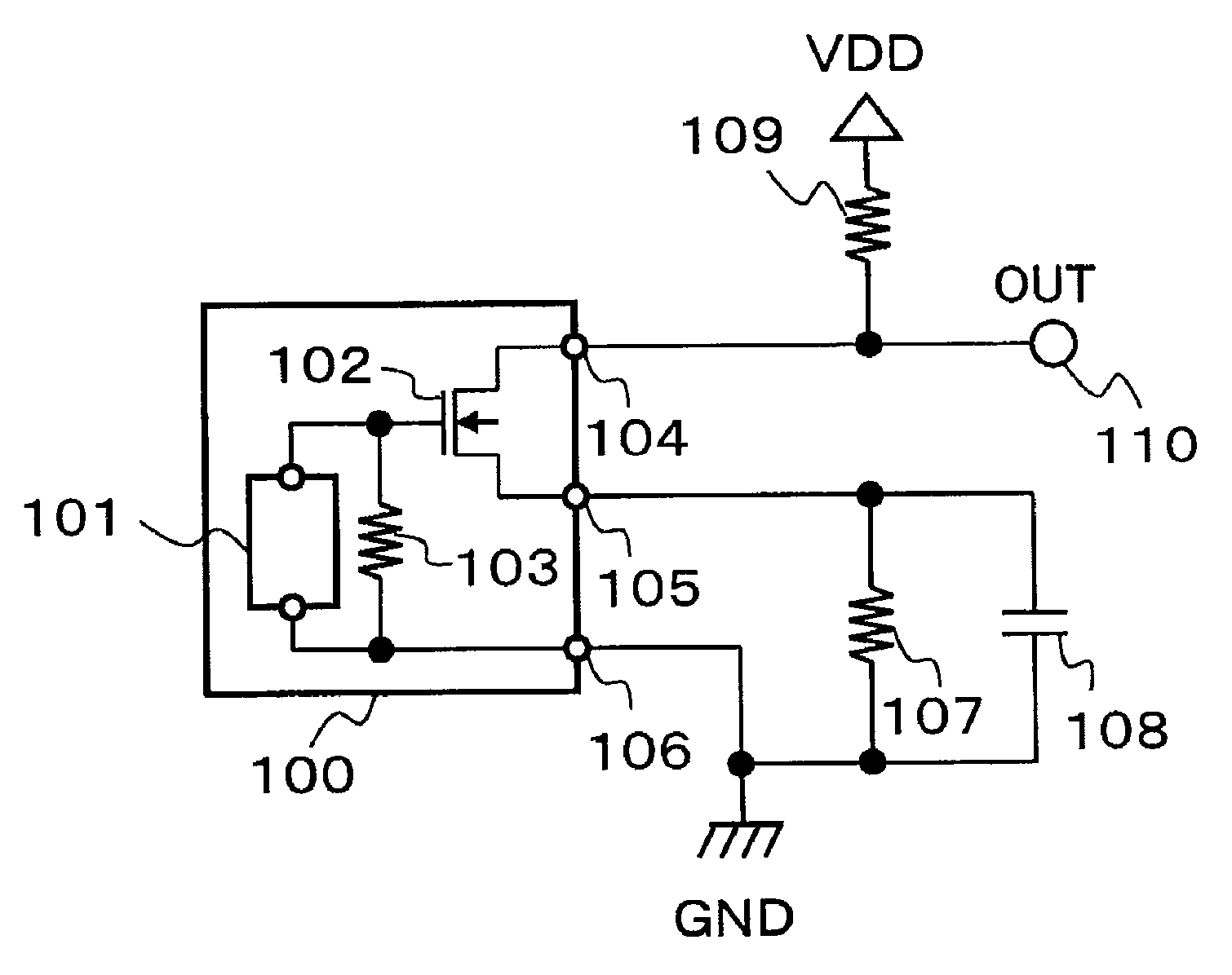
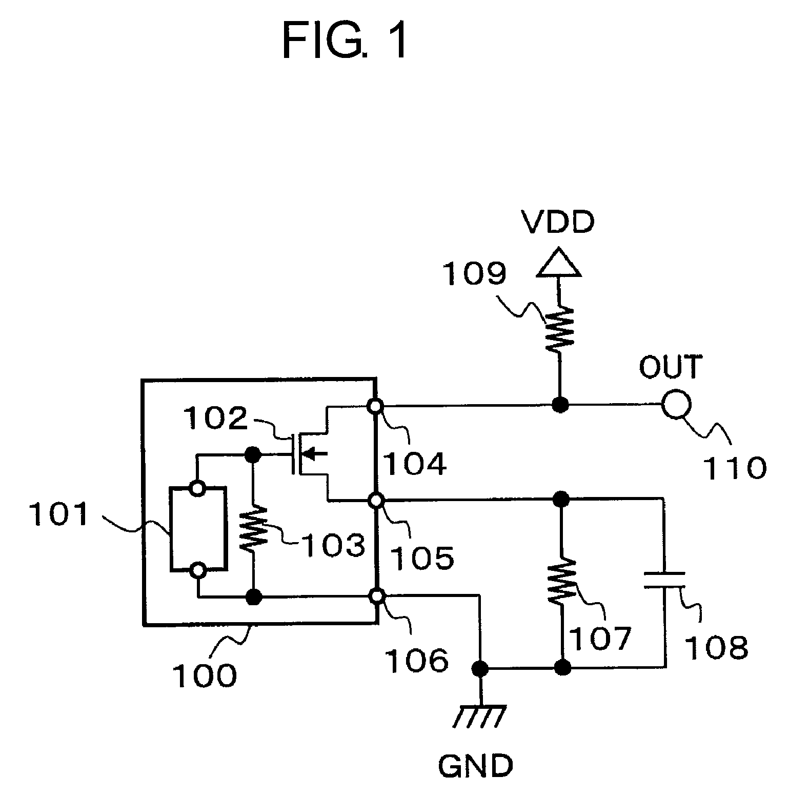
[0018]FIG. 1 is a circuit diagram of an infrared detector using a pyroelectric infrared detection element according to this embodiment.

[0019]The infrared detector according to this embodiment includes a pyroelectric infrared detection element 100, resistors 107 and 109, a capacitor 108, and an output terminal 110.

[0020]The pyroelectric infrared detection element 100 includes a pyroelectric element 101, an NMOS transistor 102, a resistor 103, a drain terminal 104, a source terminal 105, and a ground terminal 106.

[0021]The NMOS transistor 102 has a gate connected to one terminal of the pyroelectric element 101 and one terminal of the resistor 103, a drain connected to the drain terminal 104, and a source connected to the source terminal 105. The other terminal of the pyroelectric element 101 and the other terminal of the resistor 103 are connected to the ground terminal 106. The d...


PUM


Abstract

Provide is an infrared detector that has a simple configuration, has a high amplification factor, and is configured to operate at low voltage. An NMOS transistor at an output stage of a pyroelectric infrared detection element serves as a common source amplifier circuit in which a source is connected to GND via a resistor and a capacitor that are connected in parallel.

Description

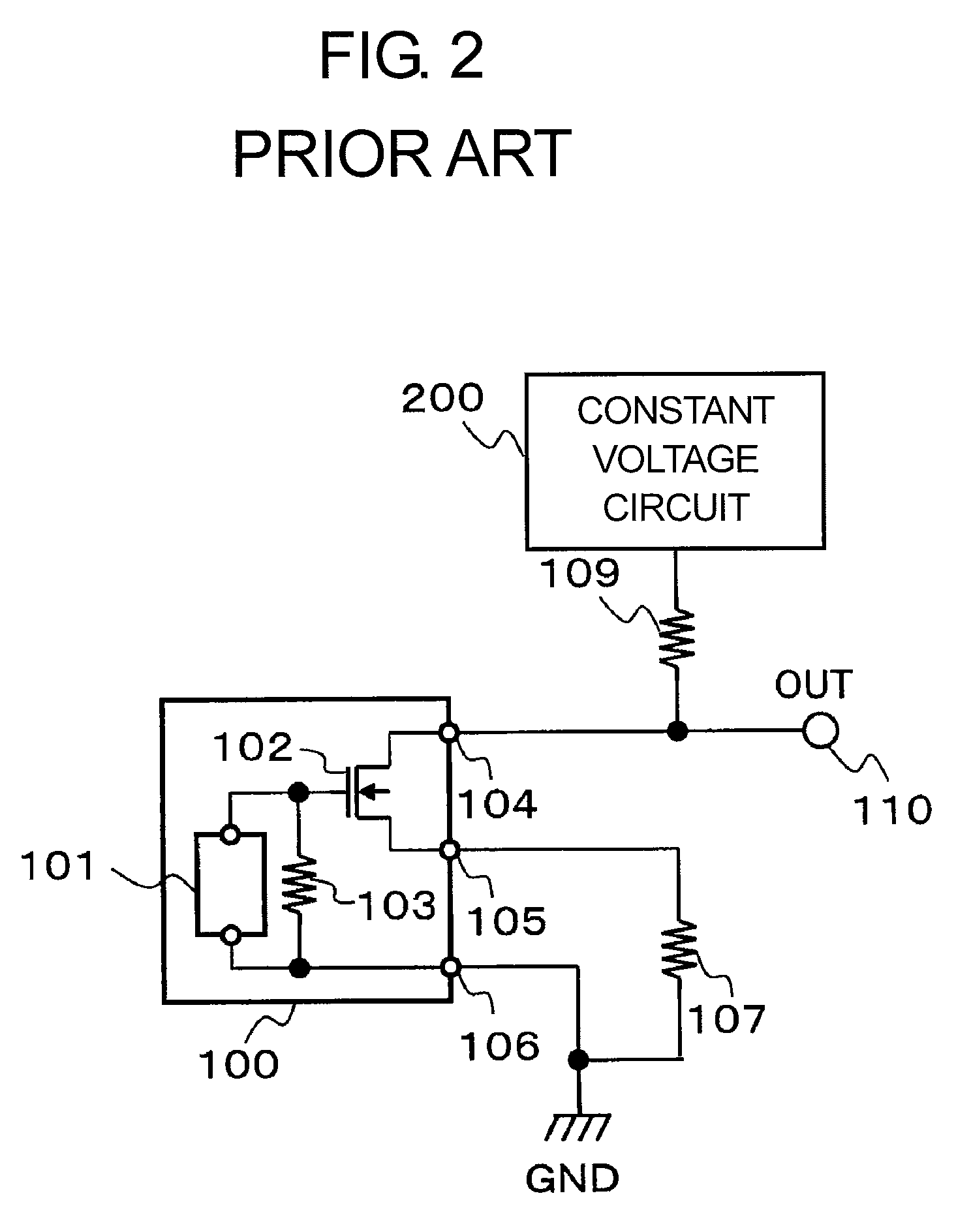
RELATED APPLICATIONS[0001]This application claims priority under 35 U.S.C. §119 to Japanese Patent Application No. 2013-178501 filed on Aug. 29, 2013, the entire content of which is hereby incorporated by reference.BACKGROUND OF THE INVENTION[0002]1. Field of the Invention[0003]The present invention relates to an infrared detector using a pyroelectric infrared detection element.[0004]2. Description of the Related Art[0005]FIG. 2 illustrates a circuit diagram of a related-art infrared detector using a pyroelectric infrared detection element.[0006]The related-art infrared detector using a pyroelectric infrared detection element includes a pyroelectric infrared detection element 100, resistors 107 and 109, a constant voltage circuit 200, and an output terminal 110.[0007]The pyroelectric infrared detection element 100 includes a pyroelectric element 101, an NMOS transistor 102, and a resistor 103.[0008]The NMOS transistor 102 has a gate connected to the pyroelectric element 101 and the ...

Claims


Application Information

Patent Timeline
Patent Type & Authority Patents(United States)
IPC IPC(8): G01J5/00G01J5/34
CPCG01J5/34
Inventor UTSUNOMIYA, FUMIYASU
Owner ABLIC INC
Learn More