Lens cap for optical module, optical module, and method for manufacturing lens cap for optical module

a technology for optical modules and lens caps, which is applied in the field of optical modules, and methods for manufacturing lens caps for optical modules, can solve the problems of deterioration of air tightness, increase of parts, and leakage, and achieve the effect of variable optical outpu

Inactive Publication Date: 2015-06-23
MITSUBISHI ELECTRIC CORP
View PDF4 Cites 1 Cited by
  • Summary
  • Abstract
  • Description
  • Claims
  • Application Information

AI Technical Summary

Benefits of technology

[0007]There is a method that changes the barrel material to a material having a smaller coefficient of linear expansion (e.g., Kovar, Fe-42Ni having a coefficient of linear expansion of 8 ppm / K or below) to reduce the amount of heat deformation. However, the problem is that the coefficient of linear expansion becomes equivalent to or less than that of the lens, which causes a force of heat caulking between the metal barrel and the lens to reduce, producing He leakage (1×10⁻⁵ Pa·m3 / s or above) and deteriorating airtightness. Note that there is also another method whereby a pre-molded press lens is fitted into a metal barrel in which a hole is formed and fixed using low melting point glass, but this method provides poor position accuracy between the lens and the barrel.
[0008]In view of the above-described problems, an object of the present invention is to provide a lens cap for an optical module, an optical module, and a method for manufacturing a lens cap for an optical module which can prevent an optical output variation and secure airtightness.
[0010]In the present invention, since the coefficient of linear expansion of the metal material is small at 100° C. or below, it is possible to reduce a lens position variation due to heat deformation of the barrel and prevent an optical output variation. At 150 to 800° C., however, the coefficient of linear expansion of the metal material is greater than that of glass, and it is therefore possible to secure airtightness making full use of the force of heat caulking between the barrel and lens.

Problems solved by technology

However, the former method cannot be used for products such as an EML chip in which a chip-mounted part is kept at a constant temperature, and the latter method has a problem that the number of parts increases.
However, the problem is that the coefficient of linear expansion becomes equivalent to or less than that of the lens, which causes a force of heat caulking between the metal barrel and the lens to reduce, producing He leakage (1×10⁻⁵ Pa·m3 / s or above) and deteriorating airtightness.
Note that there is also another method whereby a pre-molded press lens is fitted into a metal barrel in which a hole is formed and fixed using low melting point glass, but this method provides poor position accuracy between the lens and the barrel.

Method used


Image

  • Lens cap for optical module, optical module, and method for manufacturing lens cap for optical module
  • Lens cap for optical module, optical module, and method for manufacturing lens cap for optical module
  • Lens cap for optical module, optical module, and method for manufacturing lens cap for optical module

Examples


Embodiment Construction

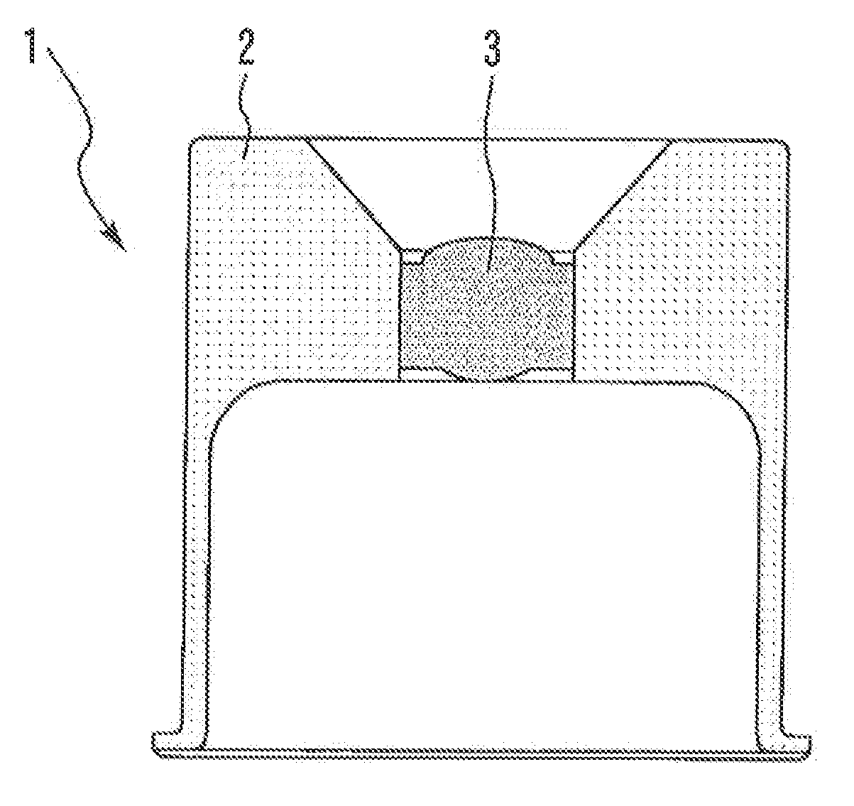
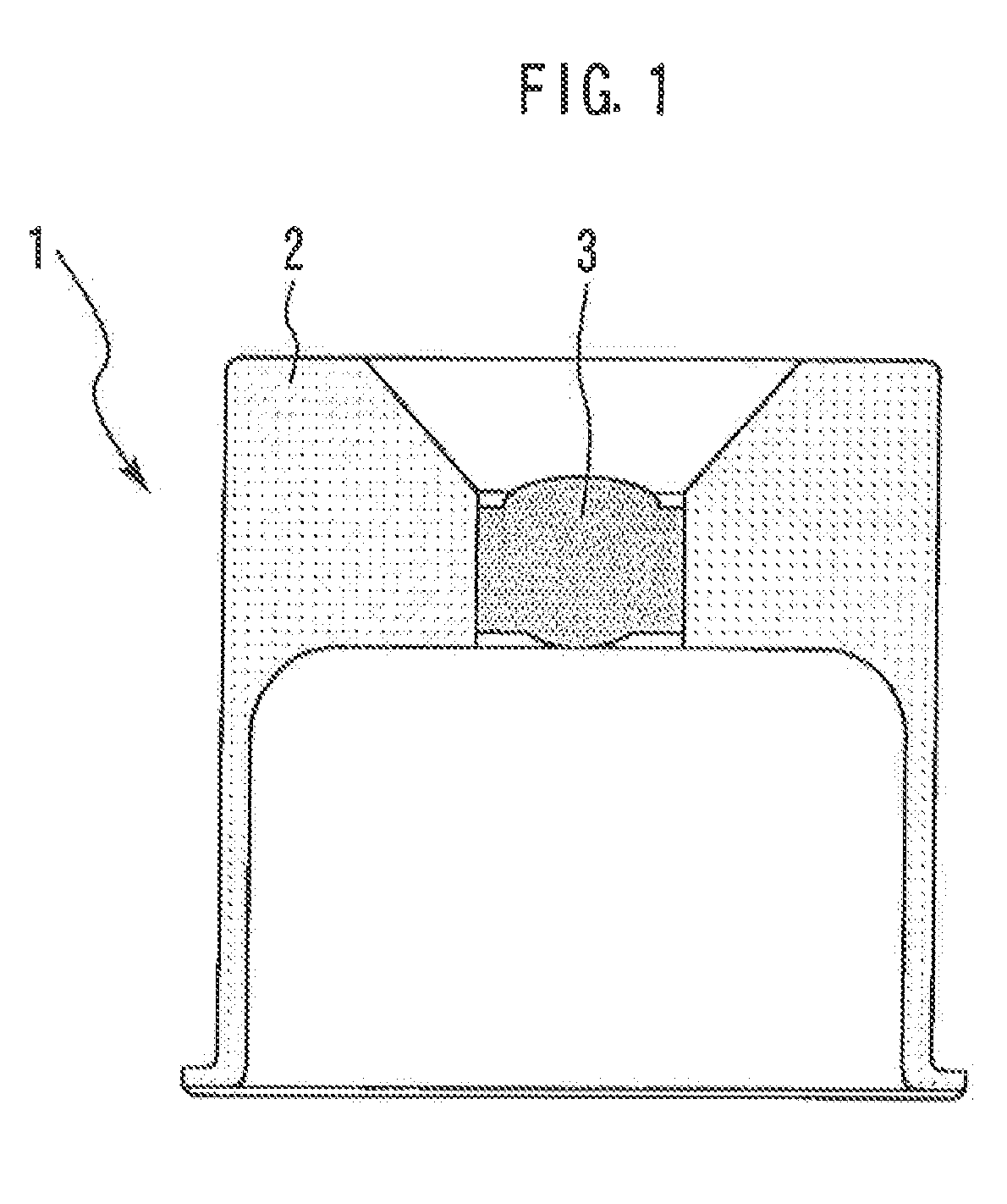
[0018]FIG. 1 is a cross-sectional view illustrating an optical module lens cap according to an embodiment of the present invention. An optical module lens cap 1 is provided with a barrel 2 and a press lens 3 held to the barrel 2. The barrel 2 is made of a metal material and the press lens 3 is made of glass. More specifically, the metal material is any one of invar, super invar and stainless steel invar (invar is a registered trademark of Aperam Alloys Imphy).

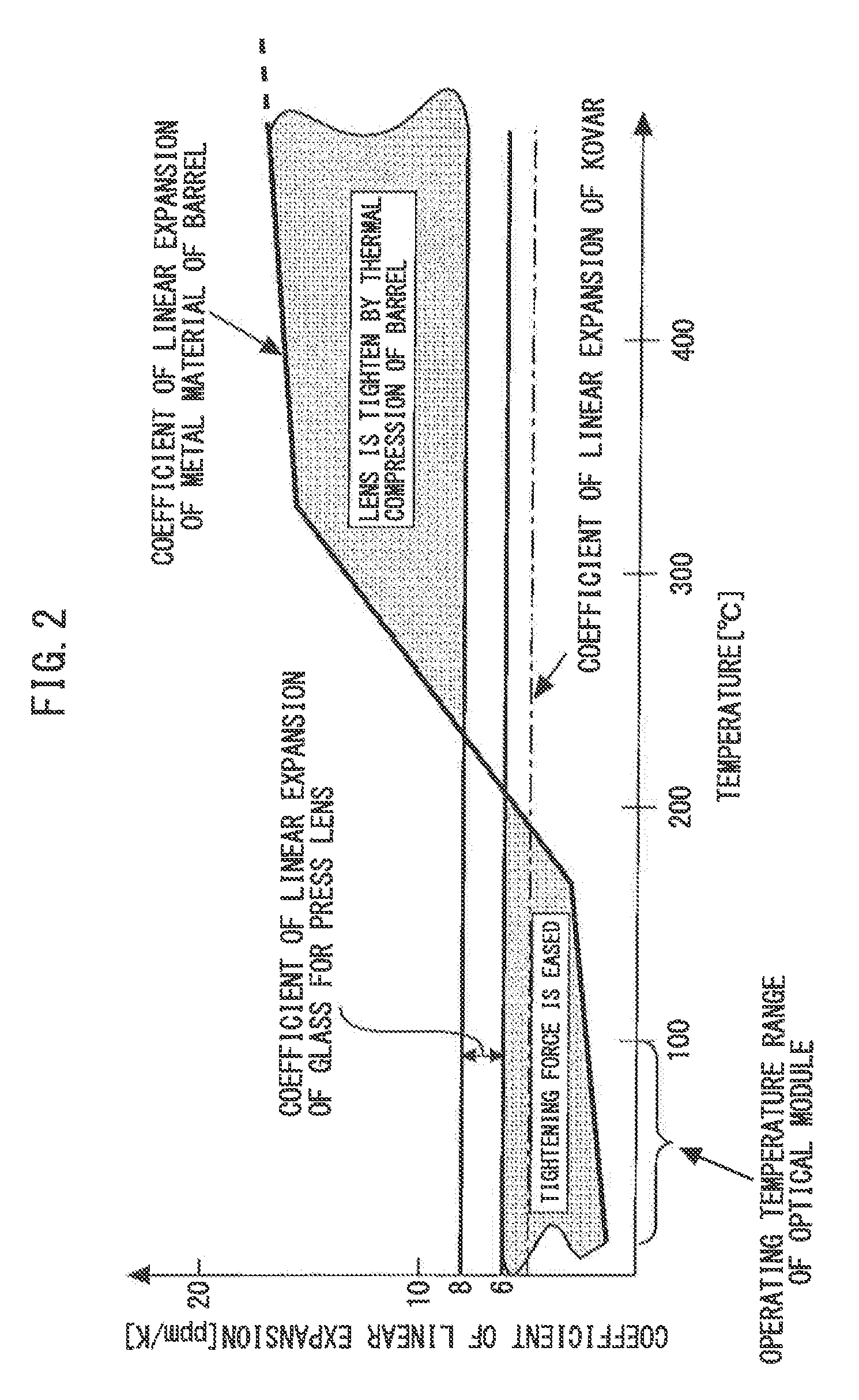
[0019]FIG. 2 is a diagram illustrating coefficients of linear expansion of the glass for the press lens and the metal material of the barrel. The coefficient of linear expansion of the glass has a relatively small temperature variation of 6 to 8 ppm / K. The coefficient of linear expansion of the metal material is 10 ppm / K or above at 150 to 800° C. (e.g., 10 to 15 ppm / K at 300° C.) and 8 ppm / K or less at 100° C. or below.

[0020]A method of manufacturing the above-described optical module lens cap 1 will be described. First, the b...


PUM

PropertyMeasurementUnit
temperatureaaaaaaaaaa
distanceaaaaaaaaaa
temperatureaaaaaaaaaa

Abstract

A lens cap for an optical module includes: a barrel of a metal material; and a press lens of glass and held in the barrel. The coefficient of linear expansion of the glass is 6 to 8 ppm / K, and the coefficient of linear expansion of the metal material is at least 10 ppm / K at 150° C. to 800° C. and no more than 8 ppm / K at up to 100° C. or below.

Description

BACKGROUND OF THE INVENTION[0001]1. Field of the Invention[0002]The present invention relates to a lens cap for an optical module, an optical module, and a method for manufacturing a lens cap for an optical module.[0003]2. Background Art[0004]Lens caps for an optical module using a conventional press lens use a material such as SUS430 or SF-20T having a coefficient of linear expansion of 10 ppm / K or more for a metal barrel (e.g., see paragraph 0014 of Japanese Patent Laid-Open No. 2009-37055). That is, a material having a greater coefficient of linear expansion than the coefficient of linear expansion of 6 to 8 ppm / K of glass is used for the barrel. This difference in the coefficient of linear expansion between the lens glass and the metal barrel causes the metal barrel to tighten the lens in a cooling process after molding of a lens at 600 to 800° C. Thus, it is possible to improve airtightness between the lens and the metal barrel.SUMMARY OF THE INVENTION[0005]In the lens caps for...

Claims


Application Information

Patent Timeline
Patent Type & Authority Patents(United States)
IPC IPC(8): G02B7/02G02B7/00C03B23/00C03C27/02
CPCG02B7/008C03C27/02C03B23/0013G02B7/028G02B7/02C03B2215/79G02B3/00G02B6/42
Inventor MATSUSUE, AKIHIRONAKAMURA, KOICHI
Owner MITSUBISHI ELECTRIC CORP
Why Eureka
Try Eureka