Supercharge Your Innovation With Domain-Expert AI Agents!

Method for characterizing a transmitting antenna of a satellite in orbit and associated system

a satellite and transmitting antenna technology, applied in the field of satellite transmitting antenna characterization, can solve the problems of isolation measurements, inability to test the transmitting antenna over the whole of its angular cover, and limited dynamic range of the transmitting antenna under test, so as to eliminate the disadvantages of their use and increase the complexity of the test.

Active Publication Date: 2015-06-23
THALES SA
View PDF16 Cites 0 Cited by
  • Summary
  • Abstract
  • Description
  • Claims
  • Application Information

AI Technical Summary

Benefits of technology

[0013]The invention does not necessitate the use of test signals on an unmodulated carrier and therefore makes it possible to eliminate the disadvantages associated with their use.
[0014]Moreover, the invention makes it possible to test the transmitting antenna of a satellite having several beams and / or several separate frequencies without necessitating the modification of test equipment and thereby increasing its complexity.
[0022]According to a particular embodiment of the invention, the payload comprises at least one receiving antenna and a reception channel and wherein the reception channel is disconnected from the receiving antenna in order to limit the influence of the noise coming from the uplink of the satellite.

Problems solved by technology

There are many disadvantages of test methods based on the use of specific test signals.
Thus, it is not possible to test the transmitting antenna over the whole of its angular cover.
However, as the radiation pattern of the receiving antenna is generally more directive than that of the transmitting antenna, the result of this is that the dynamic measuring range of the transmitting antenna under test is limited to the dynamic range available in the automatic gain control loop.
Moreover, the isolation measurements, that is to say the characterizing of the transmitting antenna for cover areas in which the gain of the antenna is very low, are also limited by the weak reception level on the receiving antenna.
Another problem associated with the use of test signals is that when it is desired to test the operation of a multi-beam transmitting antenna or of an antenna transmitting at several frequencies, this necessitates the generation of multi-carrier test signals and therefore a device for generating such signals, which increases the complexity of the test system.
Finally, the generation of a test carrier can interfere with other adjacent satellites and this necessitates overall frequency coordination.

Method used


Image

  • Method for characterizing a transmitting antenna of a satellite in orbit and associated system
  • Method for characterizing a transmitting antenna of a satellite in orbit and associated system
  • Method for characterizing a transmitting antenna of a satellite in orbit and associated system

Examples


Embodiment Construction

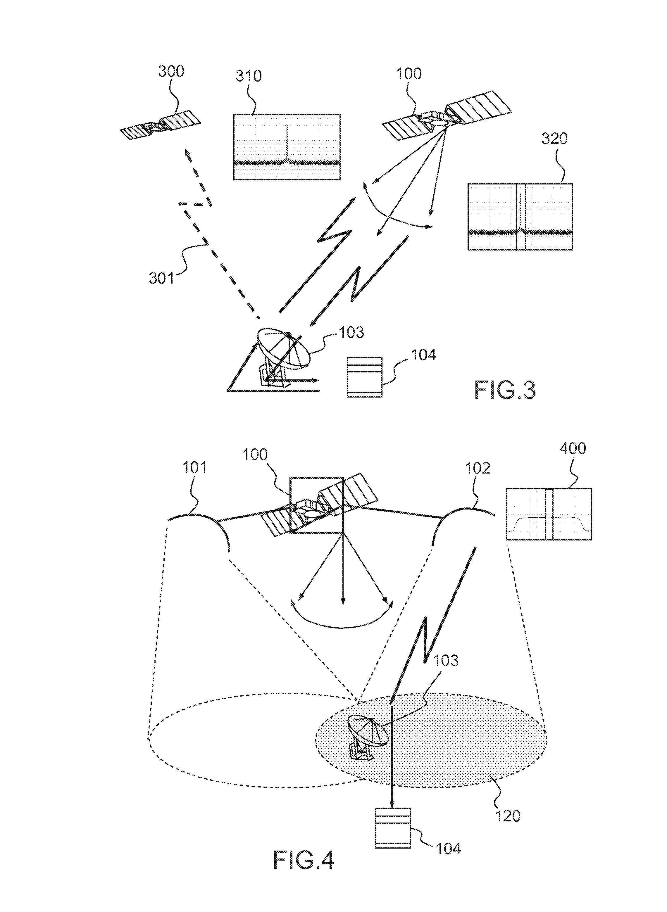
[0037]FIGS. 1, 2 and 3 show, in several diagrams and graphs, the principle of a known method of testing the transmitting antenna of a satellite in orbit and its disadvantages as already mentioned in the introduction section of the present application.

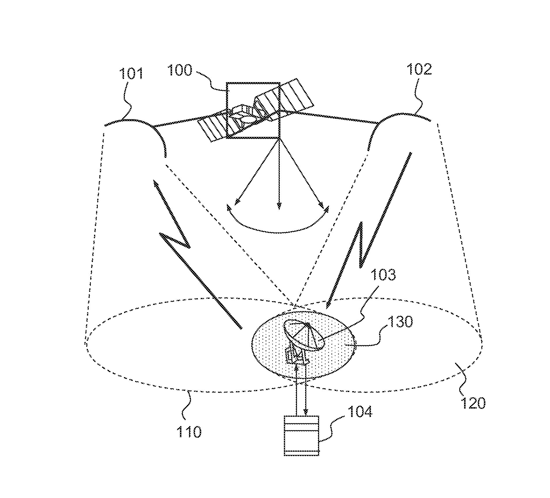
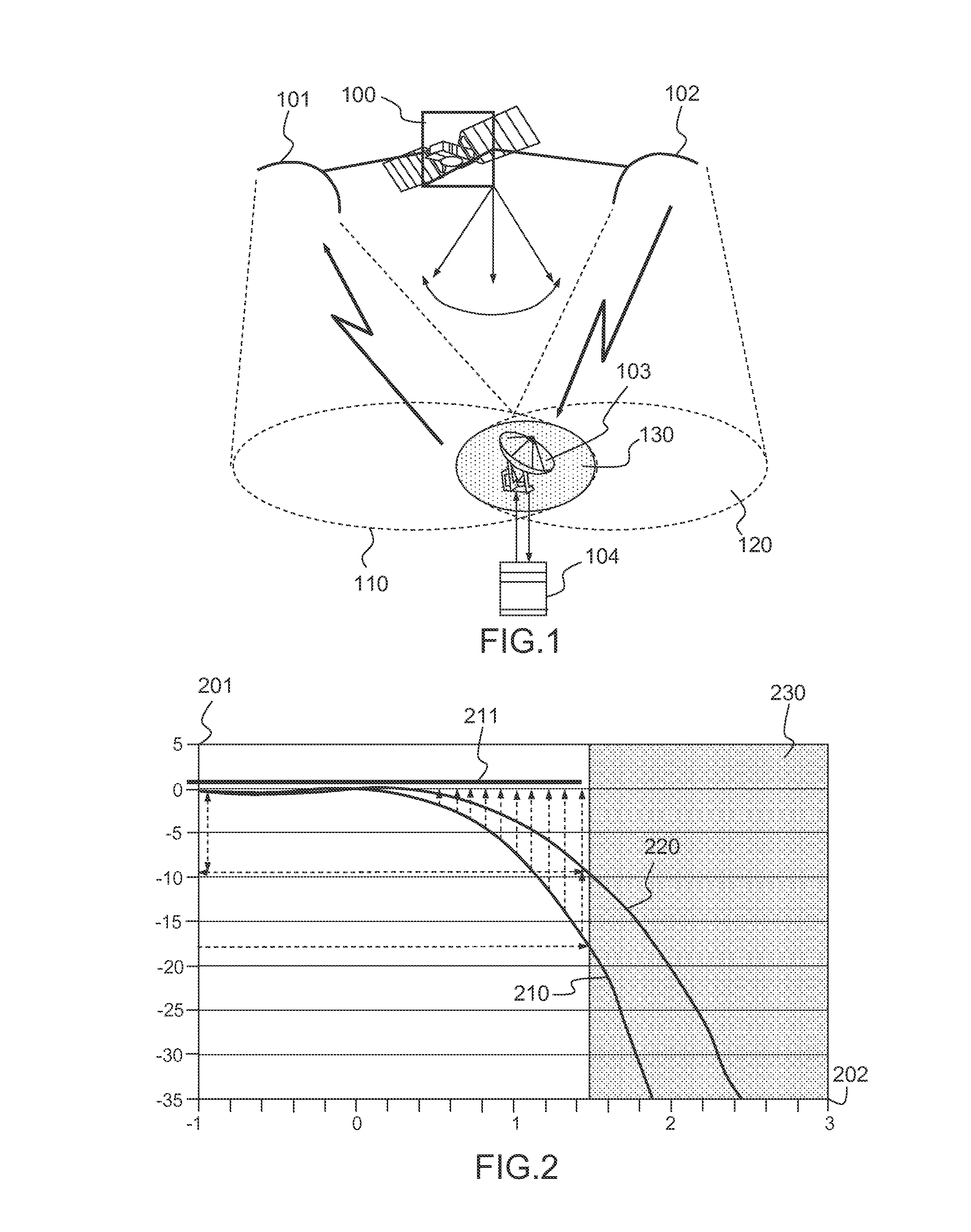
[0038]FIG. 1 shows, in a diagram, the principle of a known method of testing the transmitting antenna 102 of a satellite 100 in orbit.

[0039]A test station 104, coupled to an antenna 103, is used for generating a test signal on an unmodulated carrier and for transmitting it on the uplink of the satellite 100. The test signal is received by the receiving antenna 101 of the satellite 100 and then retransmitted by the transmitting antenna 102 of the satellite 100 via the downlink. The signal is received by the antenna 103 of the test station 104 which carries out measurements on it making it possible to characterize the antenna pattern of the transmitting antenna 102.

[0040]As explained above, a disadvantage of this method is that the testab...


PUM


Abstract

A method for characterizing a transmitting antenna of a satellite in orbit comprising a payload comprising signal amplification means, includes: configuring the said amplification means to generate thermal noise at the input of the transmitting antenna; acquiring, by means of a ground station, the signal transmitted by the transmitting antenna on the downlink of the satellite over a predetermined time period; during the said predetermined time period, controlling the said satellite in orbit in order to impart on it an angular bias of predetermined variation and recording this variation; correlating the measurement of the signal transmitted on the downlink and the variation of angular bias of the satellite in order to derive therefrom the gain variations of the transmitting antenna as a function of the angular bias of the satellite.

Description

CROSS-REFERENCE TO RELATED APPLICATION[0001]This application claims priority to foreign French patent application No. FR 1202393, filed on Sep. 7, 2012, the disclosure of which is incorporated by reference in its entirety.FIELD OF THE INVENTION[0002]The invention relates to a method and a system for testing the payload of a satellite in orbit. More precisely, the invention relates to the characterizing of the transmitting antenna of a satellite in orbit.[0003]The field of the invention is that of methods and systems making it possible to test the nominal operation of a transmitting antenna of a satellite in orbit, that is to say to characterize the radiation pattern of the antenna and to compare it with expected operational specifications.[0004]The invention is notably applied for testing a telecommunications satellite in orbit but also any satellite whose payload is composed by at least one repeater and an antenna for transmitting in the direction of a downlink.BACKGROUND[0005]The ...

Claims


Application Information

Patent Timeline
Patent Type & Authority Patents(United States)
IPC IPC(8): H04B7/185
CPCH04B7/18519H04B7/1851H04B7/185H04B7/18513G01R29/08G01R29/10
Inventor TESSANDORI, STEPHANE
Owner THALES SA
Features
  • R&D
  • Intellectual Property
  • Life Sciences
  • Materials
  • Tech Scout
  • Unparalleled Data Quality
  • Higher Quality Content
  • 60% Fewer Hallucinations
Learn More