Structure of a spindle of a machining center

a technology of machining center and spindle, which is applied in the direction of attachment milling devices, manufacturing tools, mechanical apparatus, etc., can solve the problems of maintenance cost, waste of power and extra energy, and reduce the inertia of the whole transmission system of the spindle, and less time to accelerate the spindle. , the effect of reducing the inertia of the whole transmission system

Inactive Publication Date: 2007-02-13
FACTORY AUTOMATION TECH CO LTD
View PDF10 Cites 0 Cited by
  • Summary
  • Abstract
  • Description
  • Claims
  • Application Information

AI Technical Summary

Benefits of technology

[0009]The spindle of the present invention has a clutch, a main spindle housing, which is directly connected to the clutch at the power input end thereof, and operable with the help of the clutch disk. A claw clutch is directly connected to the power source instead of hydraulic systems for passing on power to the tool shank housing for the same to change from a released position to a clamped position and vice versa; thus, inertia of the whole transmission system of the spindle can be reduced, and it takes less time to accelerate the spindle. There are fewer coiled springs fitted around the pull rod of the present spindle than the pull rods of conventional spindles. Because no hydraulic system is used in the present spindle, there won't be any disadvantage of hydraulic systems in using the spindle, e.g. waste of power and consumption of extra energy, undesirable effects of high temperature hydraulic oil on machine precision, and cost of maintenance.

Problems solved by technology

Because no hydraulic system is used in the present spindle, there won't be any disadvantage of hydraulic systems in using the spindle, e.g. waste of power and consumption of extra energy, undesirable effects of high temperature hydraulic oil on machine precision, and cost of maintenance.

Method used


Image

  • Structure of a spindle of a machining center
  • Structure of a spindle of a machining center
  • Structure of a spindle of a machining center

Examples


Embodiment Construction

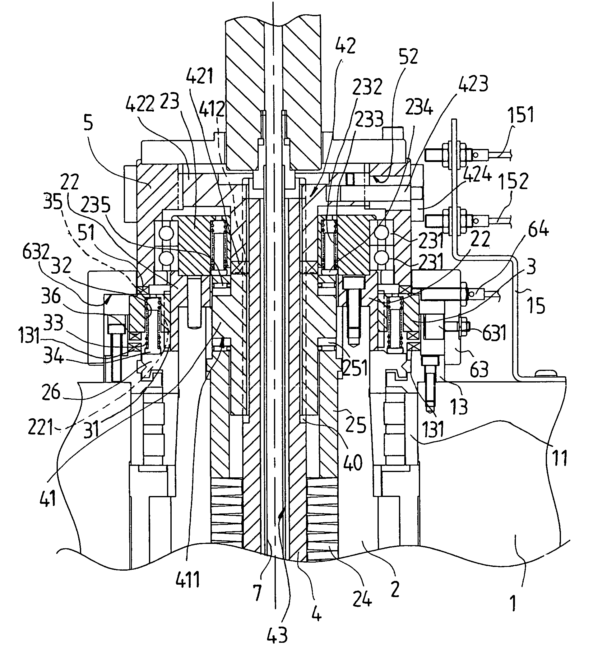
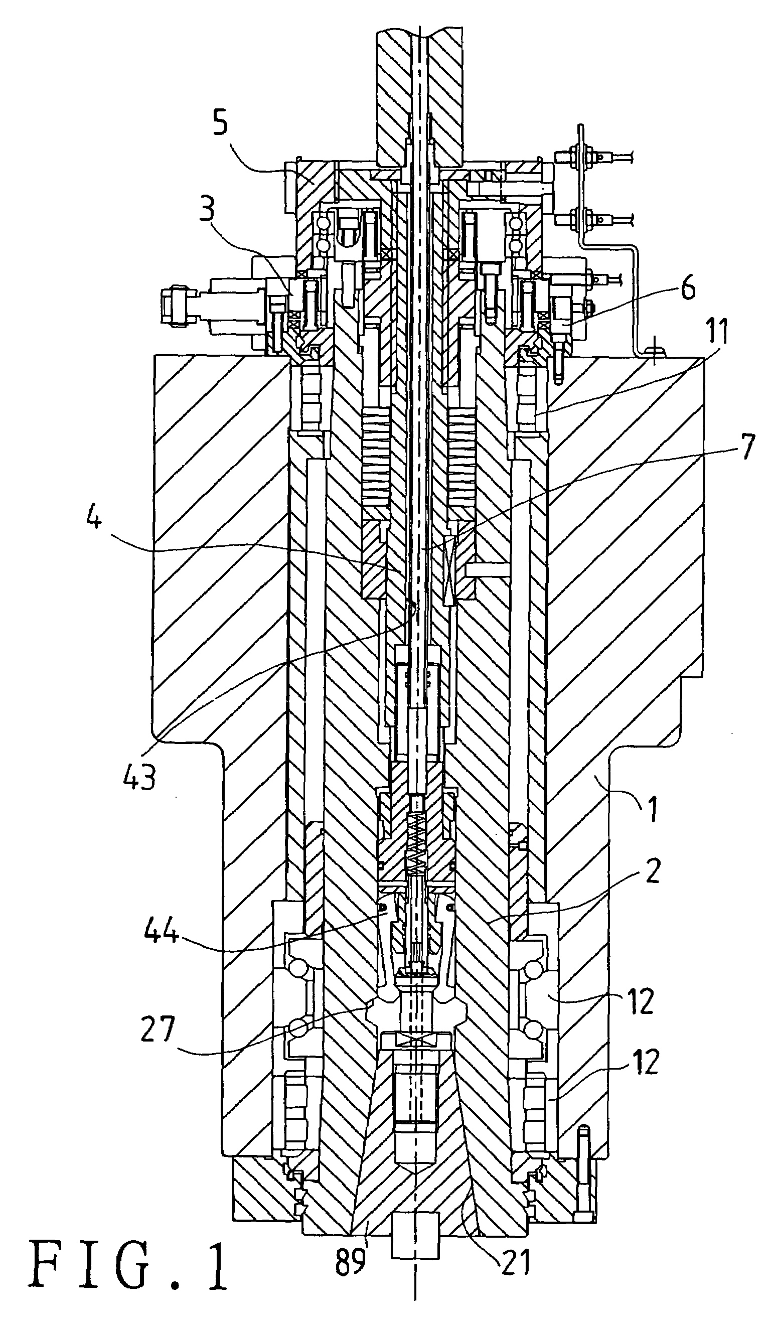
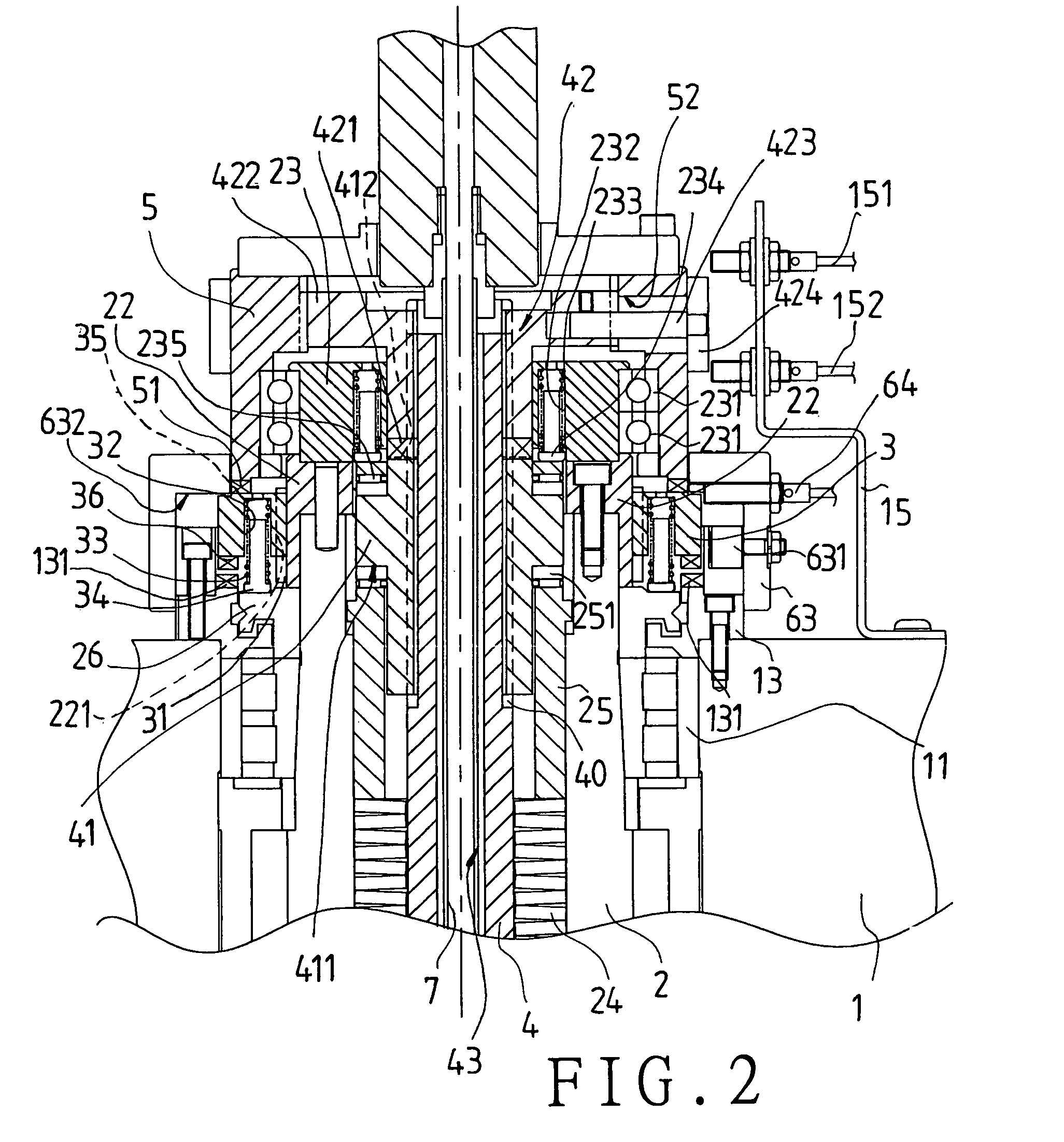
[0027]Referring to FIG. 1, a preferred embodiment of a spindle of a machining center in the present invention includes a spindle seat 1, a main spindle housing 2, a clutch 3, a pull rod 4, a claw clutch 5, a cam ring seat 6, and a guide tube 7.

[0028]Referring to FIGS. 1 to 3, the spindle seat 1 has several axial holes, and bearings 11, and 12 fitted onto the axial holes.

[0029]The main spindle housing 2 is fitted to the bearings 11, and 12, and has a cone-shaped hole 21 at a lower end for connection with a tool shank housing 89. The main spindle housing 2 has a shaft coupling 22, and a bearing support 23 at an upper end, and has coiled springs 24, and a moving spacer ring 25 held therein. External spline keys 221 are arranged outsides the shaft coupling 22 for movable connection with internal spline keys 31 of the clutch 3. In addition, a spacing element 26 is arranged between the shaft coupling 22 and the bearing 11. The bearing support 23 has a bearing 231 fitted on outer side ther...


PUM

PropertyMeasurementUnit
elastic forceaaaaaaaaaa
poweraaaaaaaaaa
clamping forceaaaaaaaaaa

Abstract

A spindle of a machining center is equipped with a clutch, which is fitted to a main spindle housing, and directly connected to a power source for separable engagement with a shaft coupling sleeve, and which is guided by sloping guiding trenches of a clutch disk such that a pull rod of the spindle is actuated for a tool shank housing to be changed between a clamped position and a released one; thus, power of the power source can be usually provided to the spindle to effect rotation of the spindle for machining a work piece, and the clutch can be operated for allowing the pull rod to be directly actuated with power of the power source without hydraulic mechanisms.

Description

BACKGROUND OF THE INVENTION[0001]1. Field of the Invention[0002]The present invention relates to a spindle of a machining center, more particularly one, which is structured in such a way that tool releasing and clamping operations can be actuated by means of a clutch, which is connected to the power source, as well as other parts instead of hydraulic mechanisms, and that the number of coil springs used in the spindle can be reduced.[0003]2. Brief Description of the Prior Art[0004]Referring to FIGS. 14 and 15, a conventional spindle 8 of a machining center includes a spindle seat 81, a spindle housing 82, a hydraulic mechanism 84, a pull rod 85, a power source 87, and a main spindle housing 83 fitted in position with the help of both the spindle seat 81 and the spindle housing 82. Oil passages 841, 842 of the hydraulic mechanism 84 are fitted in internal holes 811 of the spindle seat 81 such that a piston 843 can be actuated by means of the hydraulic mechanism 84, which piston 843 is...

Claims


Application Information

Patent Timeline
Patent Type & Authority Patents(United States)
IPC IPC(8): B23Q3/12B23B31/26B23B31/28B23C1/00
CPCB23B31/265B23B31/28Y10T409/309464B23B2270/022Y10T279/27B23B2260/044
Inventor LU, YUNG-HSIANG
Owner FACTORY AUTOMATION TECH CO LTD
Why Eureka
Try Eureka