Centrifugal fan
a centrifugal fan and fan body technology, applied in the direction of machines/engines, stators, liquid fuel engines, etc., can solve the problems of difficult to reduce the size of the blower, and achieve the effect of reducing the radial dimension shortening the axial distance, and reducing the size of the centrifugal fan
- Summary
- Abstract
- Description
- Claims
- Application Information
AI Technical Summary
Benefits of technology
Problems solved by technology
Method used
Image

Examples
first preferred embodiment
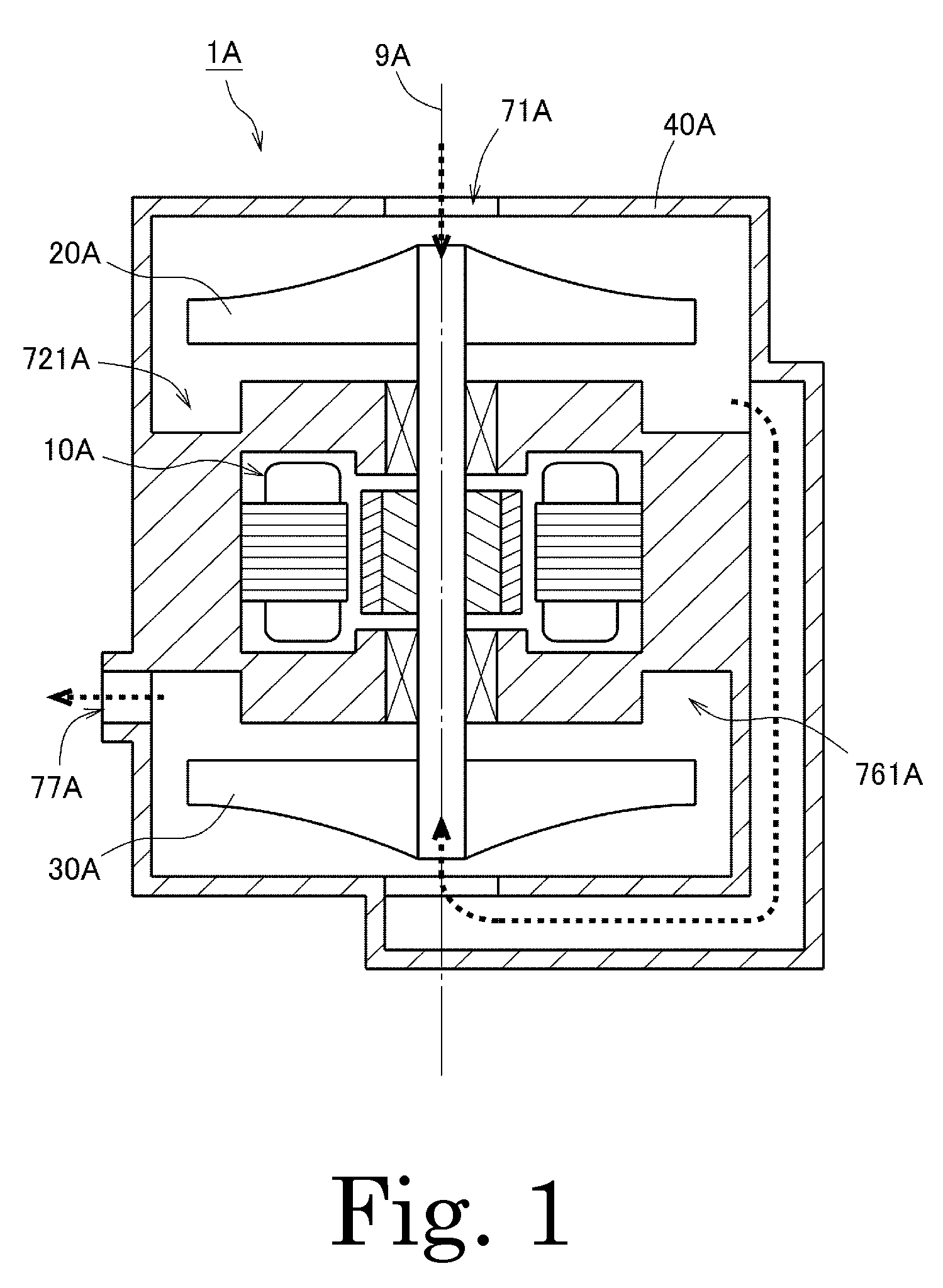
[0023]FIG. 1 is a vertical section view showing a centrifugal fan 1A according to a first preferred embodiment of the present invention. Referring to FIG. 1, the centrifugal fan 1A preferably includes a motor 10A, an upstream side impeller 20A, a downstream side impeller 30A, and a housing 40A. The motor 10A, the upstream side impeller 20A, and the downstream side impeller 30A are accommodated within the housing 40A. The downstream side impeller 30A is arranged below the upstream side impeller 20A. The upstream side impeller 20A and the downstream side impeller 30A are rotated about a center axis 9A by the motor 10A.
[0024]The housing 40A preferably includes a first intake port 71A through which a gas (such as, for example, air, oxygen, nitrogen, etc.) is drawn from the outside and an exhaust port 77A through which the gas is discharged to the outside. A flow path to bring the first intake port 71A and the exhaust port 77A into communication with each other is provided inside the hou...
second preferred embodiment
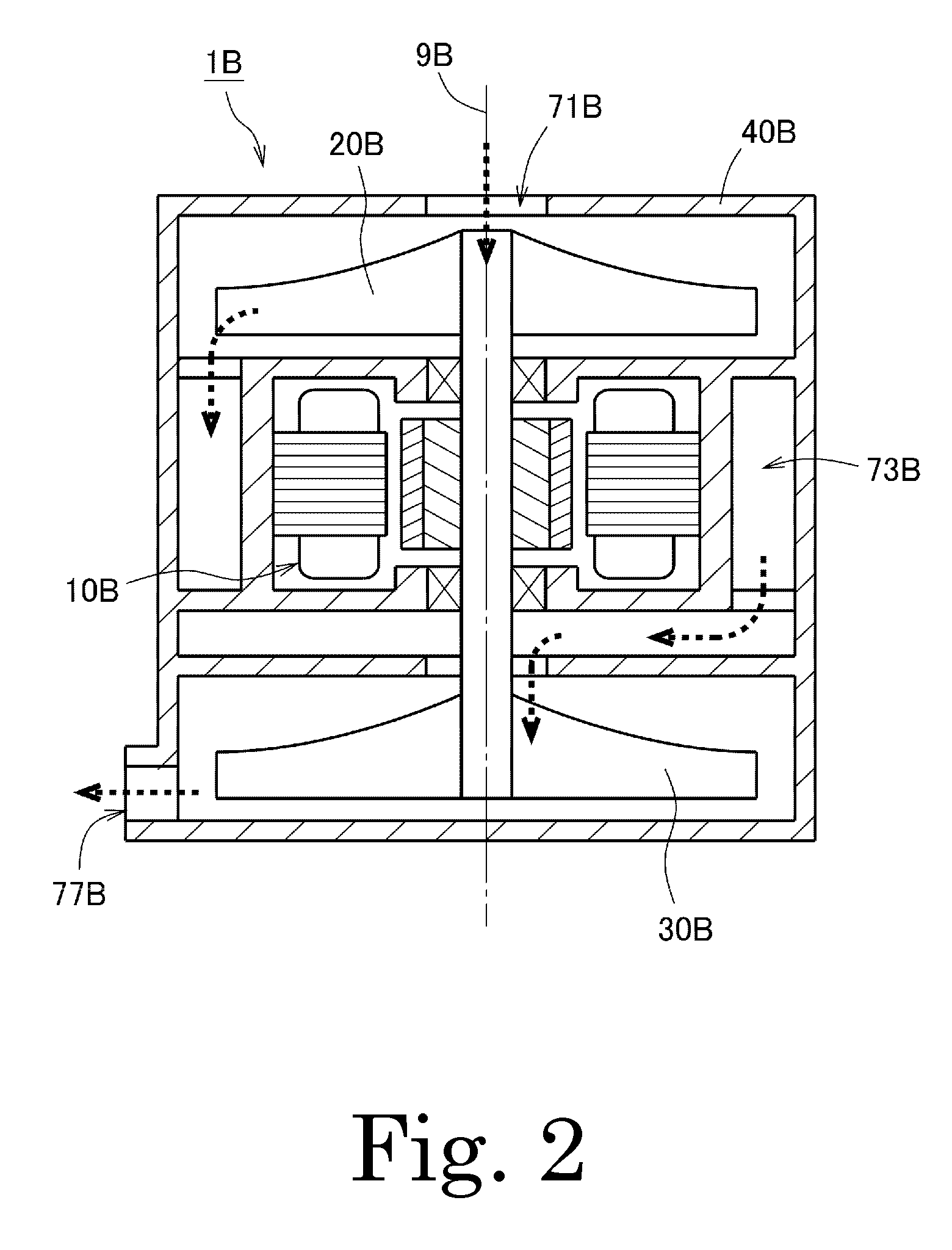
[0026]FIG. 2 is a vertical section view showing a centrifugal fan 1B according to a second preferred embodiment of the present invention. Referring to FIG. 2, the centrifugal fan 1B preferably includes a motor 10B, an upstream side impeller 20B, a downstream side impeller 30B, and a housing 40B. The motor 10B, the upstream side impeller 20B and the downstream side impeller 30B are accommodated within the housing 40B. The downstream side impeller 30B is arranged below the upstream side impeller 20B. The upstream side impeller 20B and the downstream side impeller 30B are rotated about a center axis 9B by the motor 10B.
[0027]The housing 40B preferably includes a first intake port 71B through which a gas (such as, for example, air, oxygen, nitrogen, etc.) is drawn from the outside and an exhaust port 77B through which the gas is discharged to the outside. A flow path to bring the first intake port 71B and the exhaust port 77B into communication with each other is provided inside the hou...
third preferred embodiment
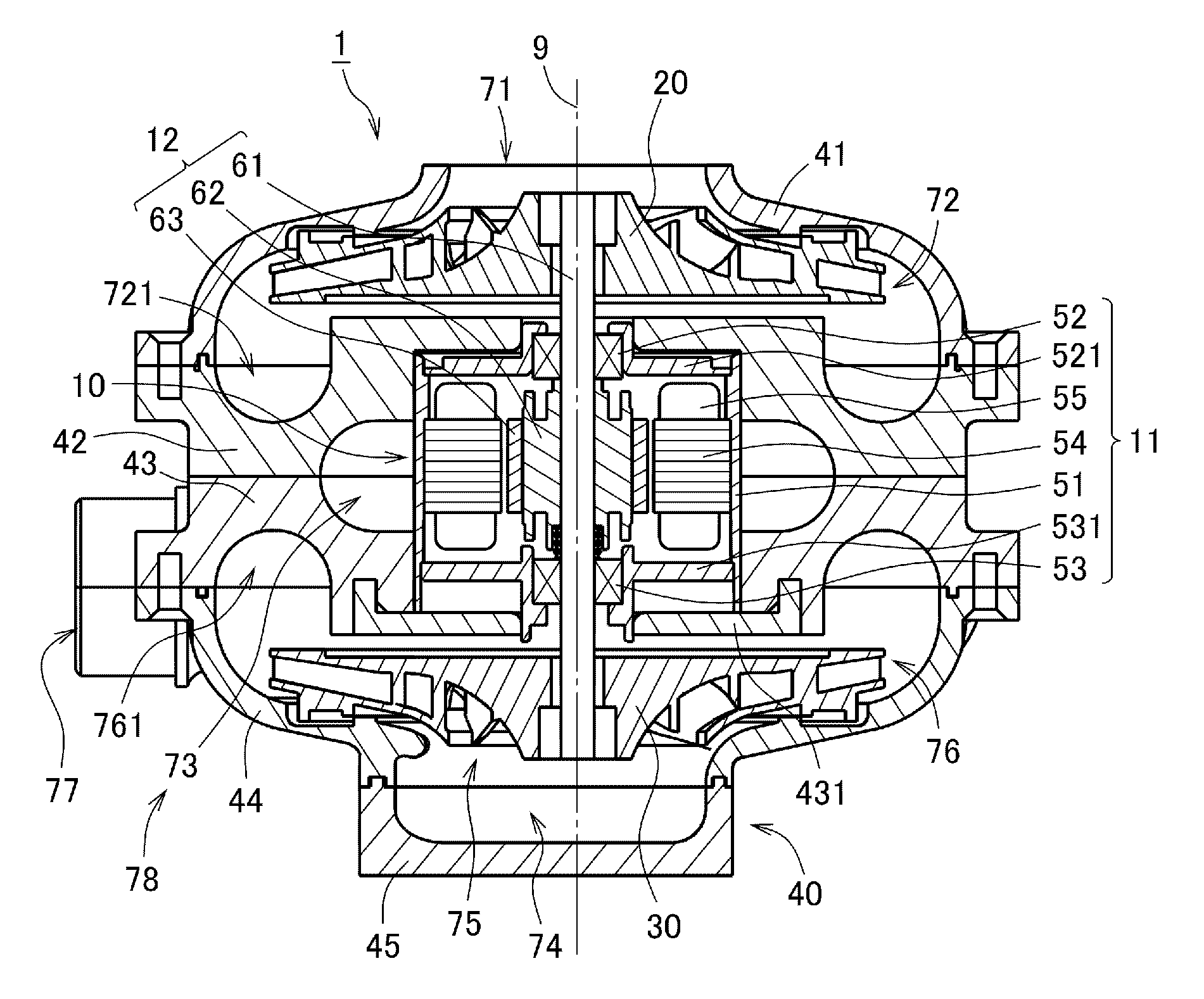
[0029]FIG. 3 is a perspective view showing a centrifugal fan according to a third preferred embodiment of the present invention. FIG. 4 is a vertical section view of the centrifugal fan 1 shown in FIG. 3.
[0030]Referring to FIGS. 3 and 4, the centrifugal fan 1 of the present preferred embodiment preferably includes a motor 10, an upstream side impeller 20, a downstream side impeller 30, and a housing 40.
[0031]The motor 10 is preferably an inner-rotor-type motor arranged to rotate the upstream side impeller 20 and the downstream side impeller 30. The motor 10 preferably includes a stationary unit 11 and a rotary unit 12 arranged inside the stationary unit 11. The stationary unit 11 is preferably fixed to the housing 40. The rotary unit 12 is supported to make rotation with respect to the stationary unit 11.
[0032]The stationary unit 11 is arranged below the upstream side impeller 20 and above the downstream side impeller 30. In the present preferred embodiment, the stationary unit 11 p...
PUM
 Abstract
Description
Claims
Application Information
 - R&D
- Intellectual Property
- Life Sciences
- Materials
- Tech Scout
- Unparalleled Data Quality
- Higher Quality Content
- 60% Fewer Hallucinations
Browse by: Latest US Patents, China's latest patents, Technical Efficacy Thesaurus, Application Domain, Technology Topic, Popular Technical Reports.
© 2025 PatSnap. All rights reserved.Legal|Privacy policy|Modern Slavery Act Transparency Statement|Sitemap|About US| Contact US: help@patsnap.com