Tesseral shim coil for a magnetic resonance system

a magnetic resonance imaging and shimming coil technology, applied in wave based measurement systems, instruments, using reradiation, etc., can solve problems such as reducing the useable portion of magnets

Active Publication Date: 2015-07-14
KONINK PHILIPS ELECTRONICS NV
View PDF18 Cites 4 Cited by
  • Summary
  • Abstract
  • Description
  • Claims
  • Application Information

AI Technical Summary

Benefits of technology

[0007]Embodiments of the invention reduce the volume required to contain the shimming coils by limiting the azimuthal span of the individual saddle coils. This allows tesseral shim coils that shim spherical harmonics the same degree and order to be combined together in the same layer resulting in a significant radial savings that increases the useable portion of a magnetic resonance imaging magnet. A tesseral shim coil is defined herein as a shim coil for shimming the tesseral or sectoral spherical harmonic components of the B0 field. Although the name is tesseral, sectoral spherical harmonics are also included as the term tesseral shim coil is also used in the art to describe coils which shim the sectoral components of the B0 field.
[0029]In another embodiment, the shim coil assembly comprises two cylindrical pieces and the shim coil assembly is adapted to be installed in a split magnetic resonance imaging system. This embodiment is advantageous, because magnetic resonance imaging systems are being used for guiding radiation therapy and charged particle beam therapy for treating cancer. Putting the shim coil assembly into two pieces allows the invention to be adapted to these types of magnetic resonance imaging systems.

Problems solved by technology

As a result the shim coils reduce the useable portion of the magnet.

Method used


Image

  • Tesseral shim coil for a magnetic resonance system
  • Tesseral shim coil for a magnetic resonance system
  • Tesseral shim coil for a magnetic resonance system

Examples


Embodiment Construction

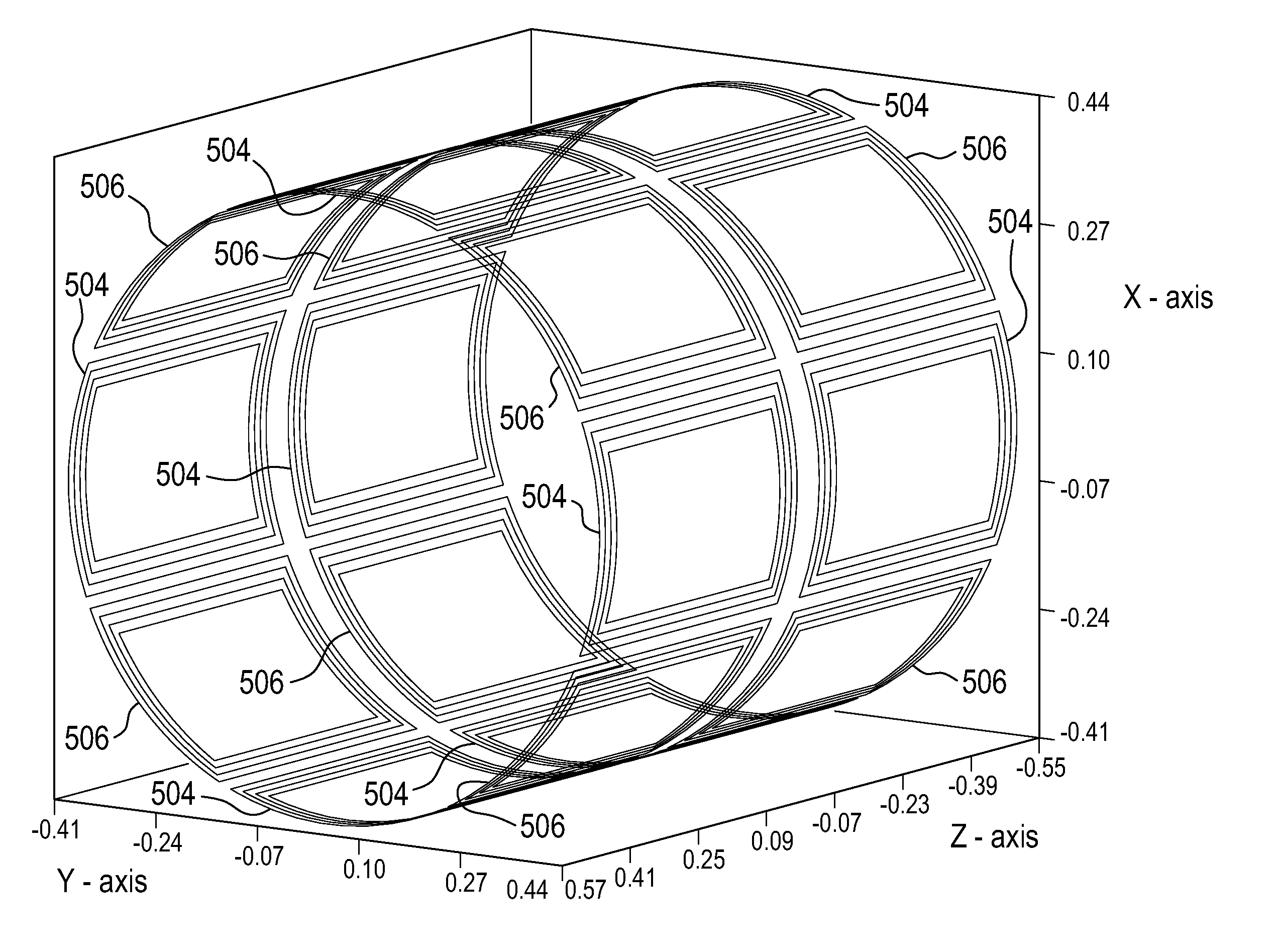
[0042]The numbering of elements is chosen such if that the two least significant digits of the numbering match then the element is either identical or performs the same function. Elements which have been discussed previously will not necessarily be discussed in description of later figures if the elements are identical or perform the same function.

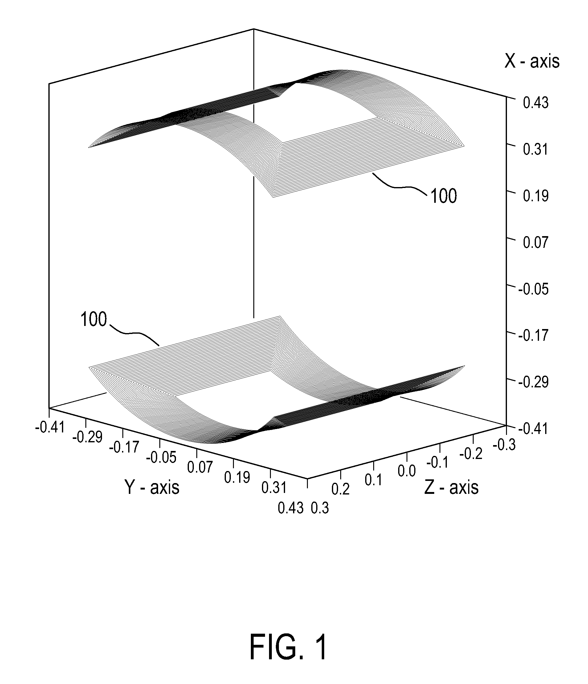
[0043]FIG. 1 shows the design of a ZX shim coil according to an embodiment of the invention. This saddle coils 100 comprising the ZX shim coil contains 36 turns extending azimuthally from 24 to 44 degrees. This is 34 degrees on average.

[0044]For evaluation of the merits of the design according to an embodiment of the invention the field coefficients for the coils shown in FIG. 1 is compared with that of a ZX saddles that contain 36 turns extending azimuthally from 49 to 71 degrees, that is 60 degrees average. Design A refers to the design that extends 60 degrees on average, and design B refers to the design shown in FIG. 1. For these calcu...


PUM

PropertyMeasurementUnit
magnetic fieldaaaaaaaaaa
radiusaaaaaaaaaa
currentaaaaaaaaaa

Abstract

A tesseral shim coil for shimming the magnetic field of a magnetic resonance system by generating the spherical harmonics of the sine and cosine type of the magnetic field, the tesseral shim coil comprising at least four saddle coils, wherein the sum of the azimuthal span of the at least four saddle coils is less than 360 degrees. First and second sets of shim coils, respectively generating sine and cosine components of the shim fields are combined into a single coil layer, thereby reducing the radial thickness of the shim coil assembly.

Description

FIELD OF THE INVENTION[0001]The invention relates to the design of tesseral shimming coils for magnetic resonance imaging systems.BACKGROUND OF THE INVENTION[0002]A static magnetic field is used by Magnetic Resonance Imaging (MRI) scanners to align the nuclear spins of atoms as part of the procedure for producing images within the body of a patient. This static magnetic field is referred to as the B0 field. It is commonly known that increasing the homogeneity of the B0 field used for performing an MRI scan increases the quality of the diagnostic images, which benefits physicians using an MRI image to diagnose a patient.[0003]To increase the homogeneity of the B0 the field in the imaging zone or region where the magnetic resonance imaging data is acquired is decomposed into spherical harmonics. The majority of magnetic resonance imaging systems have cylindrical symmetry, but the spherical harmonics have a closed form. Individual coils are designed to adjust or shim a single spherical...

Claims


Application Information

Patent Timeline
Patent Type & Authority Patents(United States)
IPC IPC(8): G01R33/341H01F5/00G01R33/3875
CPCG01R33/3875
Inventor KONIJN, JANMULDER, GERARDUS BERNARDUS JOZEF
Owner KONINK PHILIPS ELECTRONICS NV
Why Eureka
Try Eureka