Image heating apparatus

a heating apparatus and image technology, applied in the field of image heating apparatus, can solve the problems of short heat-conduction path from the heat generating source to the toner, high heat efficiency, and inability to meet the needs of the fixing member,

Active Publication Date: 2015-07-14
CANON KK
View PDF16 Cites 1 Cited by
  • Summary
  • Abstract
  • Description
  • Claims
  • Application Information

AI Technical Summary

Benefits of technology

[0007]A principal object of the present invention is to provide an image heating apparatus capable of properly sliding a magnetic flux suppressing member.

Problems solved by technology

Further, the above-proposed type of device is also characterized in that a heat-conduction path from the heat generating source to the toner is short, and therefore heat efficiency is high.
That is, during the fixing, the temperature of the fixing member is maintained at a predetermined temperature in the sheet passing region, and therefore there is a fear that the fixing member is excessively increased in temperature in the non-sheet passing region.
Thus, when the wax is accumulated at a groove portion of the screw shaft, it becomes difficult to properly slide the magnetic flux suppressing member.

Method used


Image

  • Image heating apparatus
  • Image heating apparatus
  • Image heating apparatus

Examples


embodiment 1

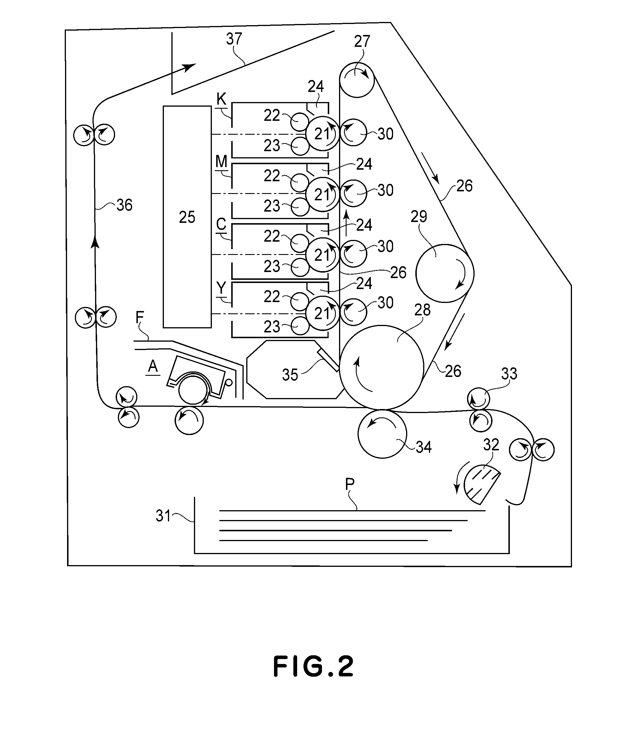
[0023]FIG. 2 is a schematic illustration of an example of an image forming apparatus in which an image heating apparatus, of an electromagnetic induction heating type, according to the present invention is mounted as a fixing device A. This image forming apparatus is a color image forming apparatus using an electrophotographic-type process.

[0024]Y, C, M and K represent four image forming portions for forming color toner images of yellow (Y), cyan (C), magenta (M) and black (K), respectively, and are arranged in this order from a lower portion to an upper portion. Each of the image forming portions Y, C, M, and K includes an electrophotographic photosensitive drum 21, a charging device 22, a developing device 23, a cleaning device 24, and the like.

[0025]In the developing device 23 of the image forming portions Y, C, M and K, toners of Y, C, M and K are accommodated.

[0026]Each drum 21 is rotationally driven in the counterclockwise direction of an arrow at a predetermined peripheral sp...

embodiment 2

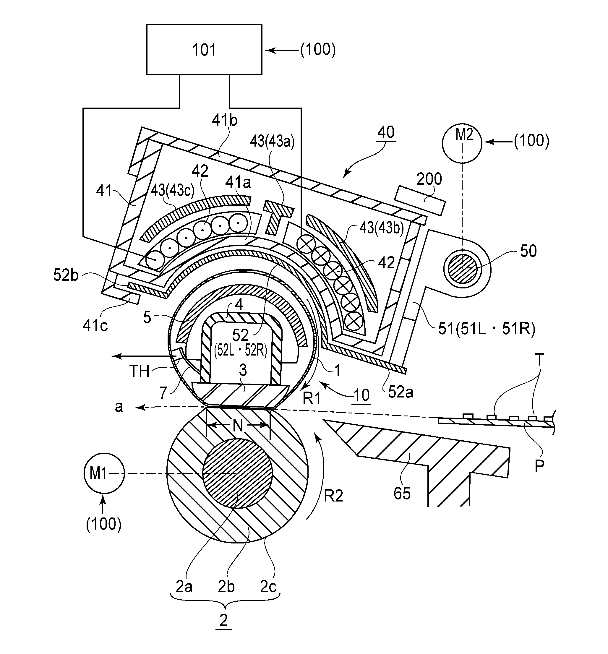
[0144]FIG. 11 is a schematic cross-sectional view of a principal portion of a fixing device A in this embodiment. The fixing device A in this embodiment is only different from the fixing device A in Embodiment 1 in that a protective member 52 for suppressing adhesion of the wax to the leading screw portions 50L and 50R is added, and therefore constitutions and operations of common portions will be omitted from description.

[0145]In the fixing device A in this embodiment, in order to suppress the adhesion of the wax, volatilized from the fixing nip N, to the leading screw portions 50L and 50R, the protective member 53 provided for covering the movable portion of the moving means is disposed. The protective member 53 has a function of suppressing the entrance of the wax into the leading screw portions 50L and 50R and of causing the wax to adhere the protective member 53. The protective member 53 is constituted by a material (e.g., metal such as aluminum or copper) having high thermal c...


PUM


Abstract

An image heating apparatus includes: a heating member configured to heat a toner image formed on a sheet by using a toner containing a wax; an exciting coil; a magnetic flux suppressing member configured to suppress a part of magnetic flux actable from the exciting coil onto the heating member; a screw shaft configured to hold the magnetic flux suppressing member and configured to slide the magnetic flux suppressing member along a longitudinal direction of the heating member; and a controller configured to control a rotational movement operation of the screw shaft so that the magnetic flux suppressing member is moved to a position depending on a width of the sheet. The controller is, during non-image heating, capable of executing an operation in a mode in which the screw shaft is rotationally moved so that the magnetic flux suppressing member is reciprocated at least once in a predetermined range.

Description

FIELD OF THE INVENTION AND RELATED ART[0001]The present invention relates to an image heating apparatus for heating a toner image formed on a sheet. This image heating apparatus is usable in image forming apparatuses such as a copying machine, a printer, a facsimile machine and a multi-function machine having a plurality of functions of these machines, for effecting image formation by using an electrophotographic-type process, an electrostatic-recording-type process, a magnetic-recording-type process, and the like.[0002]In the following description, as the image heating apparatus, a fixing device (apparatus) will be described as an example. A type of device in which heat is generated by Joule heat by generating an eddy current in a fixing member by an exciting coil as a means for heating the fixing member (rotatable heating member) has been conventionally proposed. In this type of device, a heat generating source can be placed very near to a toner, and therefore compared with a conv...

Claims


Application Information

Patent Timeline
Patent Type & Authority Patents(United States)
IPC IPC(8): G03G15/20
CPCG03G15/2053G03G15/2042
Inventor SUGAYA, KENJIROU
Owner CANON KK
Why Eureka
Try Eureka