Landing gear provided with a stiffener for increasing its stiffness in roll, and an aircraft

a technology of rolling stiffness and landing gear, which is applied in the direction of landing gear, aircraft components, skis/runners, etc., can solve the problems of non-uniform distribution, danger of instability on the ground, so as to limit the deformation of the central portion and increase the roll stiffness of landing gear

Inactive Publication Date: 2015-07-21
EUROCOPTER
View PDF8 Cites 6 Cited by
  • Summary
  • Abstract
  • Description
  • Claims
  • Application Information

AI Technical Summary

Benefits of technology

[0041]The limiter means are then secured to the central portion of the cross-member. Furthermore, the stiffener comprising at least one main hinge for hinging each connecting rod of the limiter means and one secondary hinge per connecting rod for hinging each connecting rod to an outside point that is outside the central portion in order to limit the deformation of the central portion as a result of a roll movement of the aircraft.
[0044]Surprisingly, such a stiffener makes it possible to increase the roll stiffness of the landing gear while having little or no impact on the vertical stiffness of the landing gear.
[0052]The limiter means thus tend to limit the deformation of the central portion. The roll stiffness of the landing gear is therefore increased.
[0060]In contrast, the gusset tends to perform a pivoting movement only during the second bending mode, in roll. A relatively simple device thus serves to hold the gusset still by eliminating such pivoting.
[0064]In the second bending mode, in roll, the outside point to which the connecting rod is hinged tends to remain stationary relative to the landing gear. Pivoting of the gusset during the second bending mode in roll thus tends to be blocked by the connecting rod of the stiffener. The gusset thus limits deformation of the central portion.

Problems solved by technology

As they rotate, the blades move away from their equilibrium positions and can thus become distributed non-uniformly.
This non-uniform distribution gives rise to unbalance by moving the center of gravity of the rotors away from the axis of rotation of the rotor.
There is a danger of instability on the ground when the resonant frequency of the fuselage in roll or in pitching comes close to the resonant frequency of oscillation |±ωδ| or |Ω−ωδ|, and this corresponds to the ground resonance phenomenon.
Nevertheless, it can be complex to adapt landing gear.
Developing skid landing gear is thus a process that is generally lengthy and difficult.
The resonant frequencies of the fuselage in roll and / or in pitching can therefore change, and thus run the risk of causing the ground resonance phenomenon to appear.
Nevertheless, such shape modifications can present the drawback of modifying the vertical stiffness of the landing gear.
It should not be forgotten that developing skid landing gear is a process that can be lengthy and expensive.

Method used


Image

  • Landing gear provided with a stiffener for increasing its stiffness in roll, and an aircraft
  • Landing gear provided with a stiffener for increasing its stiffness in roll, and an aircraft
  • Landing gear provided with a stiffener for increasing its stiffness in roll, and an aircraft

Examples


first embodiment

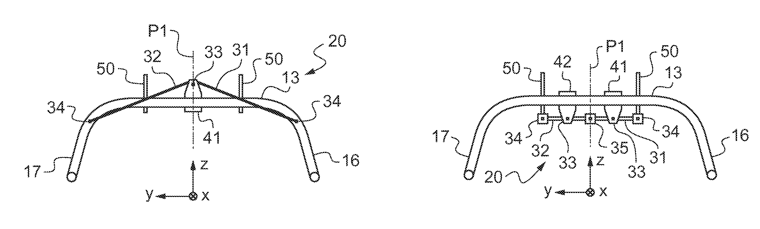
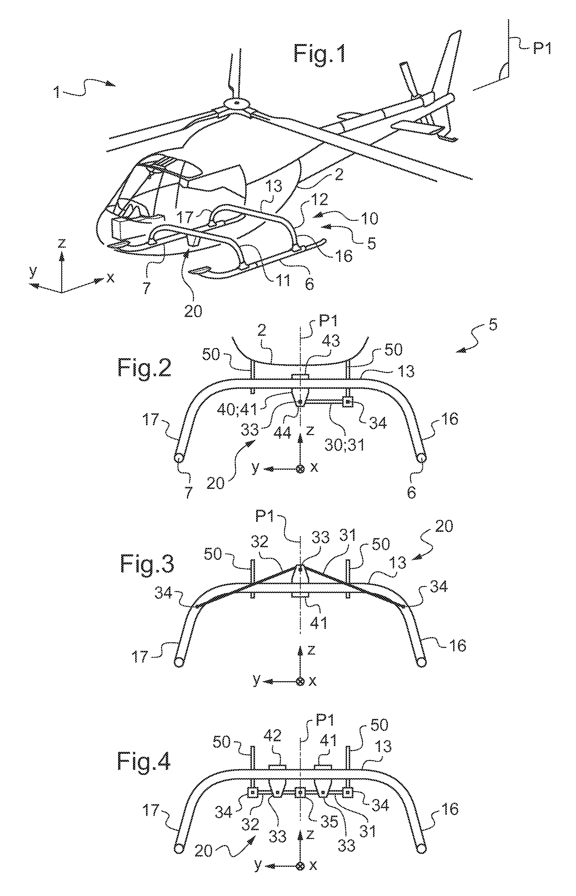
[0113]In a first embodiment as shown in FIGS. 2 and 3, a stiffener comprises a single gusset 41.

[0114]The gusset 41 is arranged in the middle of the central portion. Consequently, the base 43 of the gusset 41 extends on either side of the plane of symmetry P1. However, the main hinge 33 of each connecting rod lies substantially in the plane of symmetry P1.

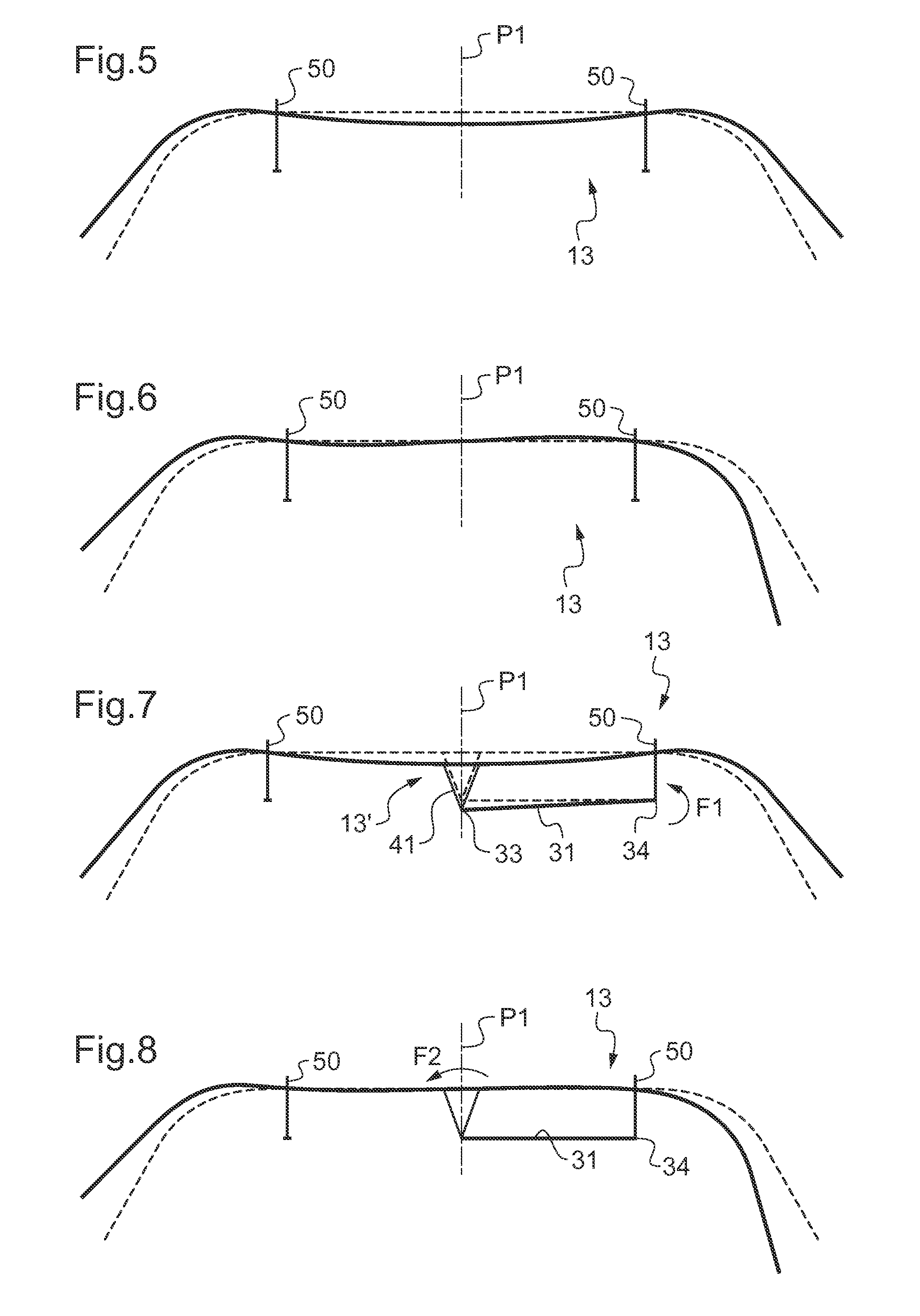
[0115]In a first variant of the first embodiment as shown diagrammatically in FIG. 2, the stiffener possesses a single connecting rod 31. This single connecting rod 31 then extends from a first end co-operating with a main hinge 33 to a second end co-operating with a secondary hinge 34.

[0116]The secondary hinge 34 is thus hinged to an outside point such as a member of the fuselage 2, or indeed a flange 50 for fastening the cross-member to the fuselage 2 in the example shown.

[0117]FIGS. 7 and 8 explain the operation of the first variant of the first embodiment by showing a cross-member in flight using a dashed line and showing the d...

second embodiment

[0137]In a second embodiment shown diagrammatically in FIG. 4, the stiffness possesses two gussets 41, 42 arranged on either side of a plane of symmetry P1 of said central portion 13.

[0138]In addition, the stiffener is provided with two connecting rods 31, 32 that are rigid, each extending from a first end that co-operates with a third hinge 35 towards a second end that co-operates with a second hinge 34. Each connecting rod is also hinged to a gusset via a main hinge 33 arranged between its first end and its second end.

[0139]By way of example, a main hinge may comprise a pivot secured to a connecting rod between its first end and its second end, the pivot co-operating with the cheeks of a gusset.

[0140]Consequently, the two connecting rods are hinged to each other by the tertiary connection 35, each secondary hinge being hinged to an outside point relative to said central portion. Each outside point is an anchor point that does not belong to the central portion of a cross-member, i....


PUM


Abstract

Aircraft landing gear (5) having a first skid (6) and a second skid (7), together with two cross-members, each having a first branch (16) secured to the first skid (6) and a second branch (17) secured to the second skid (7), and a central portion (13) secured to the downward first branch (16) and to the second branch (17). The landing gear (5) has at least one stiffener (20) with at least one connecting rod (30) and at least one limiter means (40) for limiting roll deformation of the central portion (13) of a cross-member, each limiter means (40) being secured to said central portion (13) of the cross-member, at least one main hinge (33) hinging each connecting rod to said limiter means and a secondary hinge (34) connecting each connecting rod to an outside point that is outside the central portion (13) in order to limit the deformation of the central portion (13) as a result of a roll movement of an aircraft (1).

Description

CROSS REFERENCE TO RELATED APPLICATIONS[0001]This application claims priority to French patent application No. FR 12 02567 filed on Sep. 27, 2012, the disclosure of which is incorporated in its entirety by reference herein.BACKGROUND OF THE INVENTION[0002](1) Field of the Invention[0003]The present invention relates to landing gear provided with a stiffener in order to increase its stiffness in roll, and to an aircraft having such landing gear. More precisely, the invention lies in the technical field of skid landing gear.[0004](2) Description of Related Art[0005]Conventionally, a rotorcraft has landing gear on which the aircraft stands when on the ground. More particularly, landing gear includes so-called “skid” landing gear provided with first and second longitudinal bearing skids. The skids are for coming into contact with the ground and they are arranged on either side of the fuselage of the rotorcraft. The first longitudinal bearing skid and the second longitudinal bearing skid...

Claims


Application Information

Patent Timeline
Patent Type & Authority Patents(United States)
IPC IPC(8): B64C25/52B64C25/58B64C25/32
CPCB64C25/52B64C25/58B64C2025/325
Inventor PRUD'HOMME-LACROIX, PIERRE
Owner EUROCOPTER
Why Eureka
Try Eureka