Screwing device having sealing elements

a technology of sealing elements and screwing devices, which is applied in the direction of threaded fasteners, screws, fastening means, etc., can solve the problems of time-consuming application on the wing box in the aircraft, the need for elaborate and expensive remedial work, and the removal of the screwing devi

Inactive Publication Date: 2015-07-21
AIRBUS OPERATIONS GMBH
View PDF25 Cites 0 Cited by
  • Summary
  • Abstract
  • Description
  • Claims
  • Application Information

AI Technical Summary

Benefits of technology

[0005]An aspect of the invention proposes a screwing device that provides as optimal a sealing function as possible while at the same time providing an optimal locking function, without having to resort to manual application of putty onto an adhesive-based screw-locking function or having to resort to a protracted curing time.

Problems solved by technology

If leakages occur, the removal of the screwing device and elaborate and expensive remedial work is necessary apart from the associated renewed curing time.
As a result of the confined space available, the narrow access, and the very large number of screw connections, the application on a wing box in an aircraft is time-consuming.

Method used


Image

  • Screwing device having sealing elements
  • Screwing device having sealing elements
  • Screwing device having sealing elements

Examples


Embodiment Construction

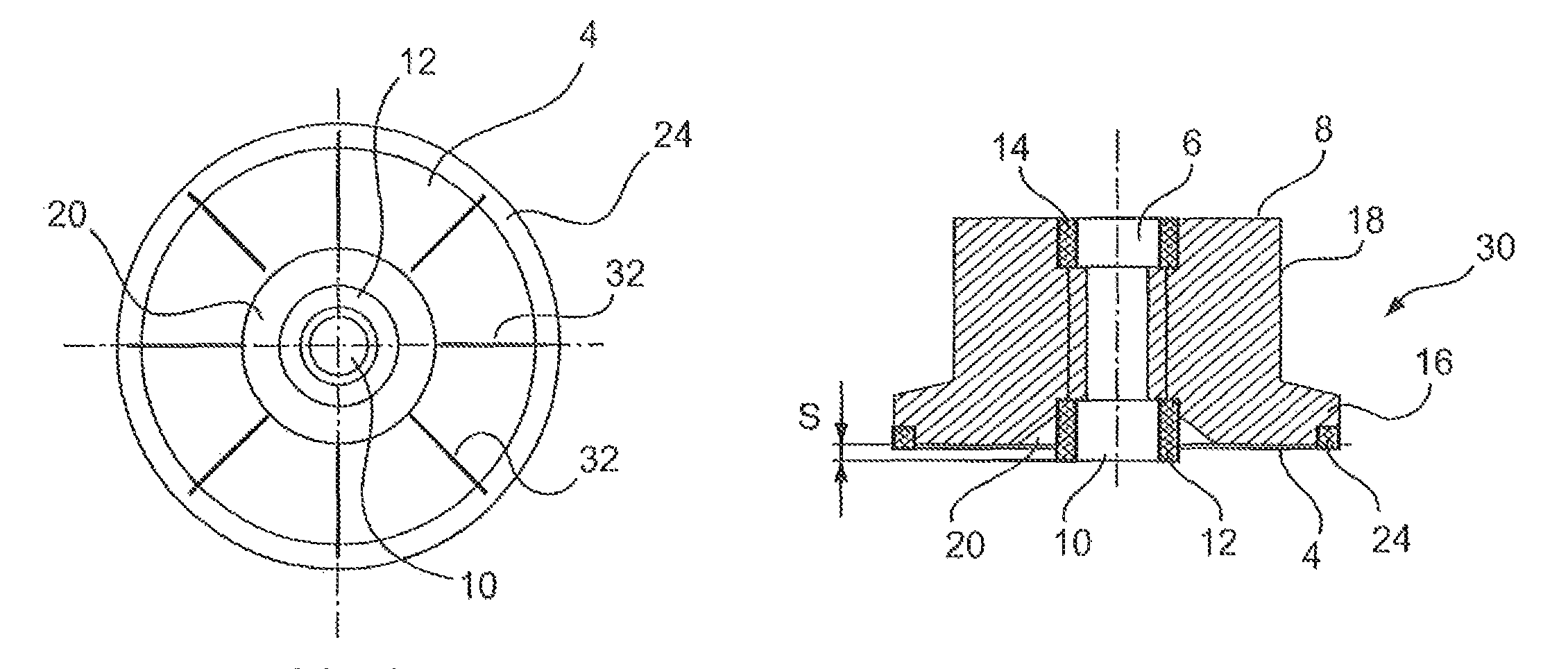
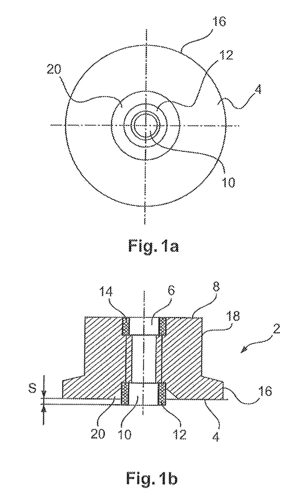
[0022]FIG. 1a-1b show a two-side illustration of a screwing device 2, with a top view of a supporting surface 4 and with a lateral section view. As an example the screwing device 2 comprises a annular supporting surface 4 from which a threaded hole 6 extends to an end surface 8 situated opposite the supporting surface 4. In the supporting surface 4 there is an insertion opening 10 through which a screw element (not shown) may be inserted into the threaded hole 6. In a region near the entry opening 10 there is a first radial sealing element 12, which in the state without a load is sleeve-shaped or ring shaped, wherein the major diameter of said sealing element 12 could approximately agree with the major diameter of the threaded hole 6 or could be somewhat exceed the aforesaid. FIGS. 1a-1b clearly show that the first sealing element 12 in an axial direction of the hole projects over the supporting surface 4 over a distance s. Consequently, the first sealing element 12 may fold togethe...


PUM

PropertyMeasurementUnit
internal diameteraaaaaaaaaa
radial distanceaaaaaaaaaa
timeaaaaaaaaaa

Abstract

A screwing device includes a threaded hole that extends from an insertion opening to an end of the screwing device, which end is opposite the insertion opening. In the region of the insertion opening a first radial sealing element is arranged that by way of the insertion opening extends outwards in an axial direction of the hole. Spaced apart from the first sealing element in an axial direction of the hole a second radial sealing element is arranged in the screwing device with the internal diameter of the second radial sealing element being smaller than the external diameter of the threaded hole. In this manner a screwing device may be provided that is self-locking, exchangeable, and fluid-proof and that is suitable especially for vehicles and in particular for aircraft.

Description

CROSS-REFERENCE TO RELATED APPLICATIONS[0001]This application claims the benefit of the filing date of U.S. Provisional Patent Application No. 61 / 738,477, filed Dec. 18, 2012, the disclosures of which application is herewith incorporated herein by reference.TECHNICAL FIELD[0002]The invention relates to a screwing device and to the use of screwing devices for a wing-fuselage connection of an aircraft.BACKGROUND OF THE INVENTION[0003]In the state of the art, screwing devices are used for a host of different applications and are highly diversified in an application-specific manner. In the manufacture and service / maintenance of vehicles, and in particular of aircraft, screwing devices are used which apart from the actual mechanical function in addition have to ensure that they do not automatically become undone as a result of vibration during operation of the vehicle. This is often ensured in that a cyanoacrylate-based adhesive is placed into the thread of a screw connection where it is...

Claims


Application Information

Patent Timeline
Patent Type & Authority Patents(United States)
IPC IPC(8): F16B39/28F16B37/04
CPCF16B39/28F16B37/04Y10T29/49963Y10T29/53
Inventor STAHL, GERDMOELLER, FRANK
Owner AIRBUS OPERATIONS GMBH
Why Eureka
Try Eureka