Pipe joint locking device

A technology for locking devices and pipe joints, which is applied in the direction of pipes/pipe joints/fittings, sealing surface connections, passing components, etc., and can solve unfavorable pipe joint connection and disassembly, crowded positions between pipe joints, loose pipe joints, and eccentricity and other problems, to achieve good fastening effect, improve strength, and prevent slack

Inactive Publication Date: 2013-05-29
GUIZHOU HONGLIN MACHINERY
View PDF5 Cites 0 Cited by
  • Summary
  • Abstract
  • Description
  • Claims
  • Application Information

AI Technical Summary

Problems solved by technology

[0002] At present, in order to lock the pipe joints used between several interface pipe joints, safety holes are usually opened on the pipe joints, and then locking wires are drawn out of the safety holes for locking. This locking method is complicated due to the product structure. The position between the assembled pipe joints is crowded, which is not conducive to the connection and disassembly of the pipe joints, and in the environment of vibration and high temperature, the locking wire is easy to break, and the pipe joints will cause slack, eccentricity, etc., so this kind of pipe joints The fastening effect of the locking method is poor, which affects the reliability of use

Method used


Image

  • Pipe joint locking device
  • Pipe joint locking device
  • Pipe joint locking device

Examples


Embodiment Construction

[0013] The present invention will be described in detail below in conjunction with the accompanying drawings.

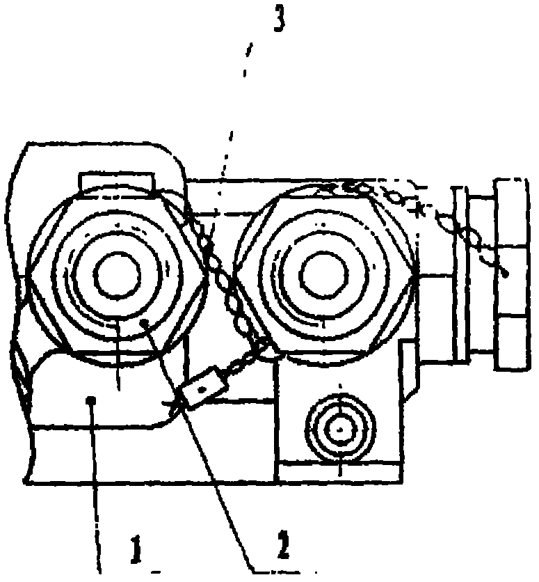
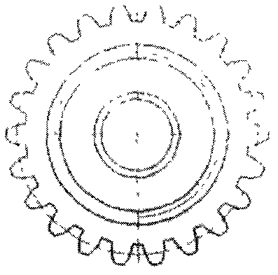
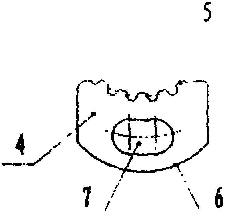
[0014] Figure 4 It is a structural schematic diagram of the pipe joint locking device of the present invention used in a certain engine accessory. In this embodiment, the pipe joint 2 with external splines is an improved version of the existing pipe joint of the accessory. The hexagonal part of the cylinder is changed into a cylinder with a certain thickness, and an external spline is formed on the outer edge of the cylinder with an involute tooth profile, and the other parts remain unchanged; the material used for the lock 4 is the same as that of the pipe joint, and the shape is a fan-shaped structure , the inner end surface 5 is a spline tooth groove structure, the number of teeth meshing with the outer spline is 4, the outer end surface 6 is arc-shaped, the arc diameter is Φ13mm, the total length of the lock 4 is 15mm, and it is in the middle of the lock sector ...


PUM


Abstract

The invention provides a pipe joint locking device, the pipe joint locking device includes a pipe joint with an external spline and a lock catch with an internal spline, wherein the pipe joint with the external spline is modification of a general six-directional pipe joint, the modification mainly includes that a six-joint part of the pipe joint is changed into a column with a certain thickness, an external spline structure is formed at the edge of the column through an involute tooth profile , and other parts are in accordance with the structure of the general six-directional pipe joint. The lock catch is made of materials the same as the pipe joint, and the lock catch is in a sector structure. An inner end face of the lock catch is in a spline tooth space structure, and an outer end face of the lock catch is in an arc shape. An elliptical hole is formed in the middle of a sector, and is used for fixing the lock catch on a shell body of an accessory through a screw.

Description

technical field [0001] The invention relates to a pipe joint locking device, which is mainly used in occasions with large vibration or high temperature. Background technique [0002] At present, in order to lock the pipe joints used between several interface pipe joints, safety holes are usually opened on the pipe joints, and then locking wires are drawn out in the safety holes for locking. This locking method is complicated due to the product structure. The position between the assembled pipe joints is crowded, which is not conducive to the connection and disassembly of the pipe joints, and in the environment of vibration and high temperature, the locking wire is easy to break, and the pipe joints will cause slack, eccentricity, etc., so this kind of pipe joints The fastening effect of the locking method is poor, which affects the reliability of use. Contents of the invention [0003] The purpose of the present invention is to provide a pipe joint locking device with hig...

Claims


Application Information

Patent Timeline
Patent Type & Authority Applications(China)
IPC IPC(8): F16L19/00
Inventor 王艳召
Owner GUIZHOU HONGLIN MACHINERY
Why Eureka
Try Eureka