Heat exchanger

a technology of heat exchanger and heat exchanger body, which is applied in the direction of indirect heat exchangers, heating types, lighting and heating apparatus, etc., can solve the problems of serious problems, impaired appearance of heat exchanger, and condensed water, so as to keep the heat exchanger from impairment of its appearance

Inactive Publication Date: 2015-07-21
DAIKIN IND LTD
View PDF14 Cites 3 Cited by
  • Summary
  • Abstract
  • Description
  • Claims
  • Application Information

AI Technical Summary

Benefits of technology

[0007]Accordingly, an object of the present invention is to provide a heat exchanger which is easy to change in dimensional settings of its fins and which is less liable to scattering of condensed water from the fins and moreover which is kept from impairment of its appearance.
[0014]Consequently, even if condensed water has scattered from the edges having the burrs thereon, the scattered condensed water can be received by the edges that are in contact with or opposition to the edges having the burrs thereon. Thus, since condensed water can be prevented from scattering outside along with winds, the heat exchanger of the invention, even when used as a heat exchanger on the indoor side of an air conditioner, can be kept from indoor scattering of the condensed water mixed in winds.
[0015]Also, in the heat exchanger of this invention, edges with burrs present thereon in the first fins or the second fins are so positioned as to be in contact with or opposition to the other edges of the first fins or the second fins, and the edges with the burrs present thereon are positioned inside. Therefore, burrs are present only on the edges that are in contact with or opposition to the second fins, and not on the other edges, among all the edges of the first fins, and moreover burrs are present only on the edges that are in contact with or opposition to the first fins, and not on the other edges, among all the edges of the second fins. Since the edges having the burrs thereon are never positioned on the outer side of the heat exchanger, the heat exchanger can be kept from impairment of its appearance.
[0016]Also, in the heat exchanger of this invention, edges with burrs present thereon in the first fins or the second fins are so positioned as to be in contact with or opposition to the other edges of the first fins or the second fins, and the edges with the burrs present thereon are positioned inside. Therefore, even if condensed water has scattered from the edges having the burrs thereon, the scattered condensed water can be received by the edges that are in contact with or opposition to the edges having the burrs thereon. Thus, since condensed water can be prevented from scattering outside along with winds, the heat exchanger of the invention, even when used as a heat exchanger on the indoor side of an air conditioner, can be kept from indoor scattering of the condensed water mixed in winds.
[0017]Further, in the heat exchanger of this invention, since the edges having the burrs thereon are never positioned on the outer side of the heat exchanger, the heat exchanger can be kept from impairment of its appearance.

Problems solved by technology

However, the above conventional heat exchanger, while having an advantage of easiness in changing dimensional settings of the fins, has a problem that because, in division of the fins, burrs are formed on an outer edge of the heat exchanger formed by dividing the perforated fins at the perforations and corresponding to places of the fins where the perforations have been separated, condensed water (dew drop water) generated on the fins during the use of the heat exchanger may scatter from the fins along the burrs.
In particular, when the conventional heat exchanger is used as a heat exchanger on the indoor side of an air conditioner, the condensed water may be scattered indoors by air blows, giving rise to a serious problem.
Further, in the conventional heat exchanger, since the edge on which the burrs are present is positioned at an outer edge of the heat exchanger, there is another problem that the appearance of the heat exchanger is impaired.

Method used


Image

  • Heat exchanger
  • Heat exchanger
  • Heat exchanger

Examples


Embodiment Construction

[0024]Hereinbelow, the present invention will be described in detail by embodiments thereof illustrated in the accompanying drawings.

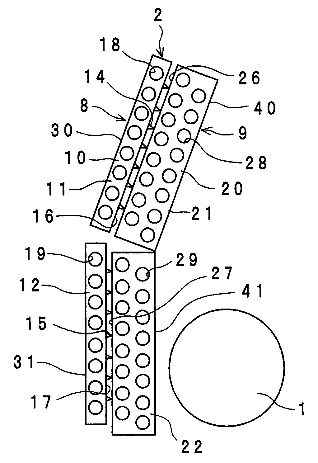
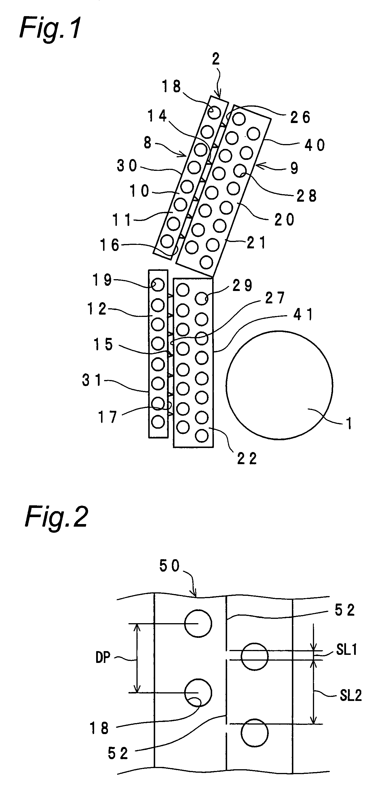
[0025]FIG. 1 is a schematic sectional view of an air conditioner which uses a heat exchanger according to one embodiment of the invention. In FIG. 1, reference numeral 1 denotes a blower fan, and 2 denotes a heat exchanger. In FIG. 1, a casing or the like in which the blower fan 1 and the heat exchanger 2 are housed is omitted for simplicity's sake.

[0026]This air conditioner is so designed that the blower fan 1 is rotated to blow out air, which serves as a heat transfer medium sucked in via the heat exchanger 2, through an unshown blowoff opening.

[0027]The heat exchanger 2 has an auxiliary heat exchanger 8 as an example of a first heat exchanger section, and a main heat exchanger 9 as an example of a second heat exchanger section.

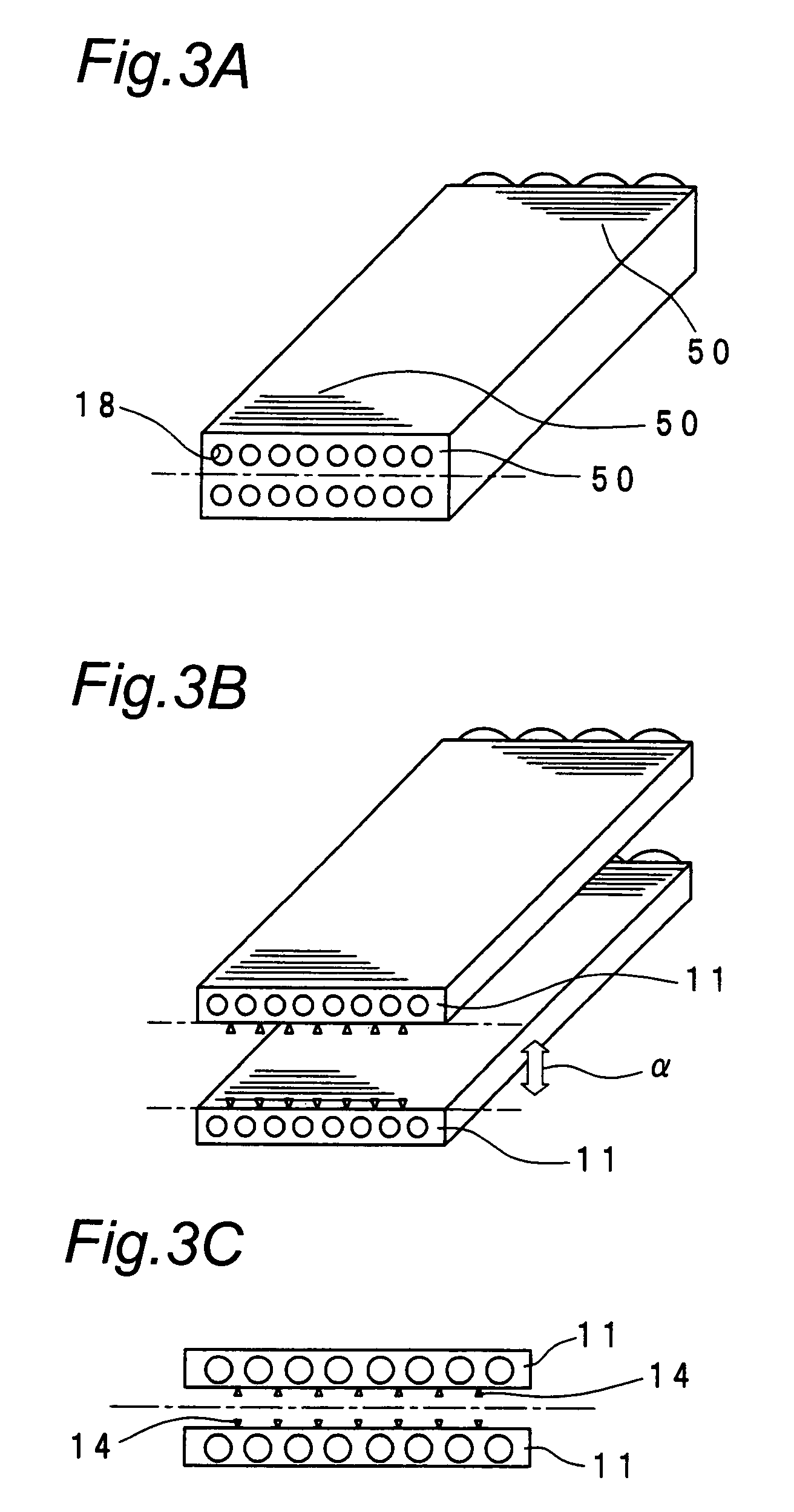
[0028]The auxiliary heat exchanger 8 has sheet-like first fins 10, and unshown first heat transfer tubes. The first fin 10, ...


PUM


Abstract

A heat exchanger includes an auxiliary heat exchanger, which has plate-shaped first fins and a plurality of first heat transfer tubes, and a main heat exchanger which has plate-shaped second fins and a plurality of second heat transfer tubes. A plurality of burrs are present at specified intervals on edges of the first fins. The auxiliary heat exchanger and the main heat exchanger are so positioned that the edges of the first fins on which the burrs are present are in contact with edges of the second fins, and the edges having the burrs present thereon are positioned on the inner side.

Description

CROSS-REFERENCE TO RELATED APPLICATIONS[0001]This U.S. national stage application claims priority under 35 U.S.C. §119(a) to Japanese Patent Application No. 2004-340326 filed in Japan on Nov. 25, 2004, the entire contents of which are hereby incorporated by reference.TECHNICAL FIELD[0002]The present invention relates to a heat exchanger. More particularly, the invention relates to a heat exchanger suitable for use in air conditioners, refrigerators, ice makers and the like.BACKGROUND ART[0003]Conventionally, there has been a heat exchanger formed by dividing perforated fins, which have perforations formed therein, at their perforations. More specifically, this heat exchanger is formed by inserting heat transfer tubes into insertion holes of a perforated fin and then separating the fin at the perforations so that two heat exchangers are formed.[0004]The conventional heat exchanger shown above, in which the fins can be separated at the places of the perforations, is easy to manufactur...

Claims


Application Information

Patent Timeline
Patent Type & Authority Patents(United States)
IPC IPC(8): F28B1/00F28D1/04F28D1/02F28F17/00F24F1/00F28F1/32F24F1/0067F24F13/22F25B39/02
CPCF28F17/005F24F1/0059F28F1/32F24F1/0067
Inventor KITAZAWA, MASAAKITAIRA, SHIGEHARU
Owner DAIKIN IND LTD
Why Eureka
Try Eureka