

Ionic electro-conductive resin and electro-conductive member for electrophotography
a technology of electrophotography and electro-conductive resin, which is applied in the direction of non-metal conductors, instruments, corona discharge, etc., can solve the problems of inability to obtain sufficient electro-conductivity in the low-temperature, low-humidity environment, and contamination of the photosensitive member due to bleeding or blooming, etc., to achieve stable formation of high-quality electrophotographic images, sufficient electro-conductivity, and high electro-conductivity
- Summary
- Abstract
- Description
- Claims
- Application Information
AI Technical Summary
Benefits of technology
Problems solved by technology
Method used
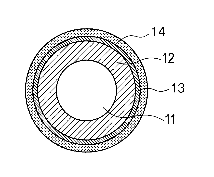
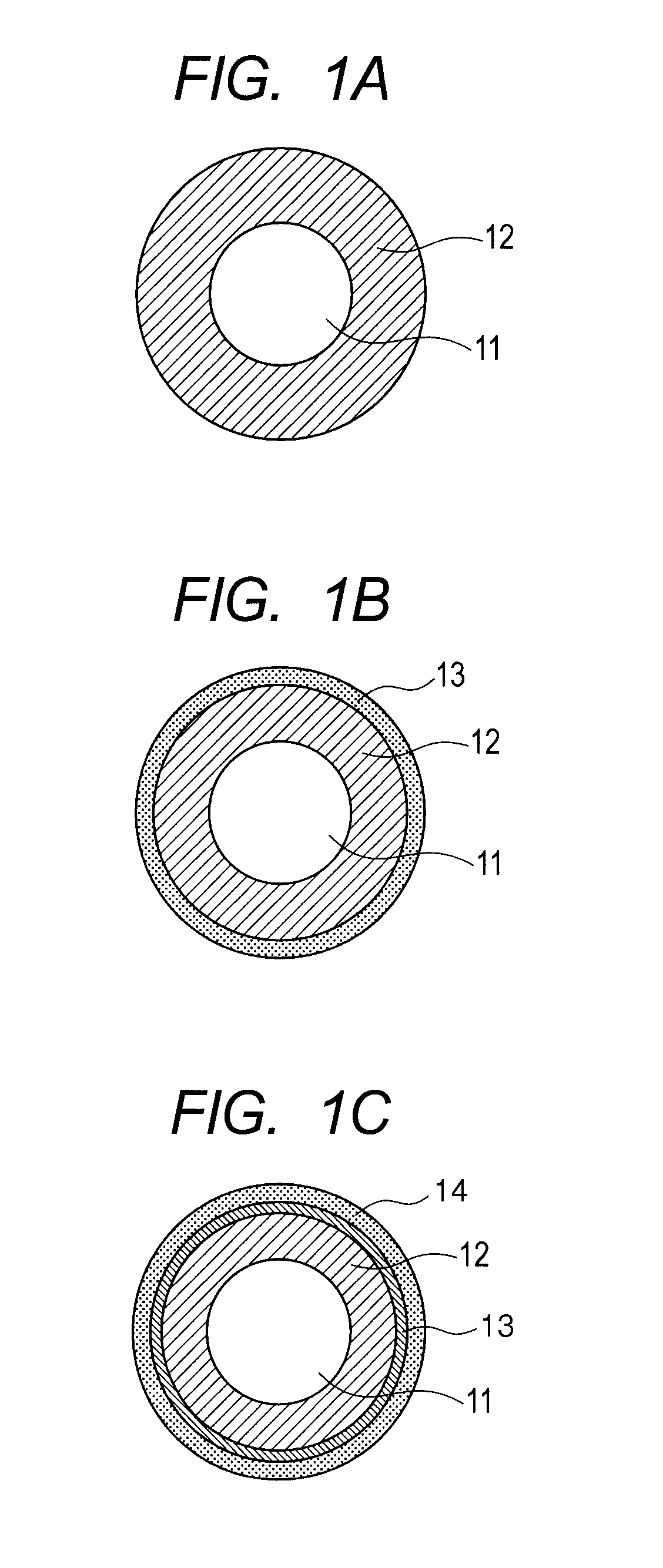
Image

Examples
example 1
[0126]Production and Evaluations of Charging Roller No. 1;
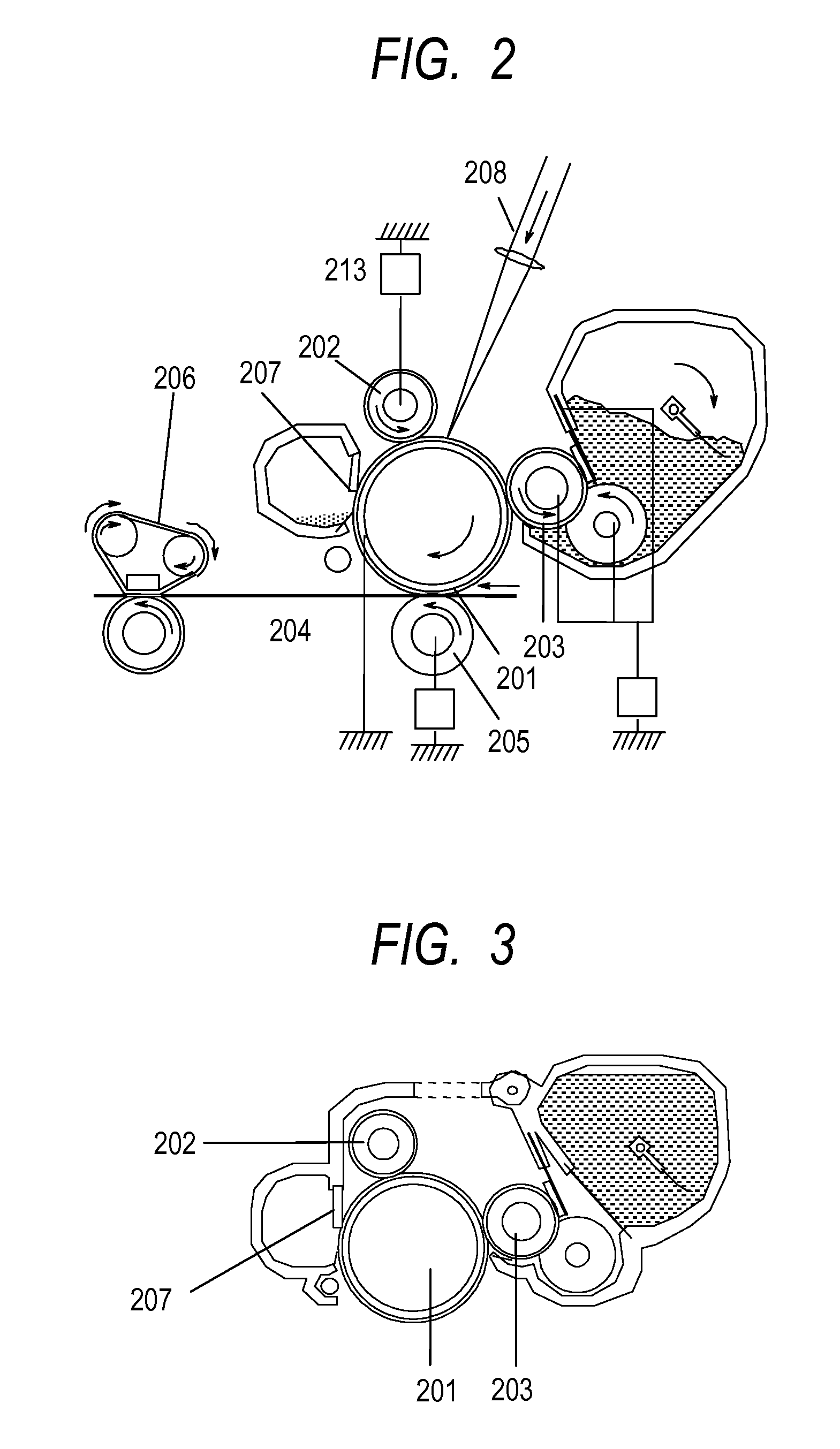
[0127]The coating liquid No. 1 was applied onto the outer peripheral surface of the rubber roller No. 1 once by dipping, and was then air-dried at normal temperature for 30 minutes or more. Next, the resultant was dried by a circulating hot air dryer set at 80° C. for 1 hour, and was then further dried by a circulating hot air dryer set at 160° C. for 3 hours.
[0128]A dipping application immersion time was regulated to 9 seconds, and a dipping application lifting speed was regulated so that the initial speed was 20 mm / s and the final speed was 2 mm / s. The speed was linearly changed with time from 20 mm / s to 2 mm / s. Thus, a charging roller No. 1 having an ionic electro-conductive resin-containing layer on the outer periphery of an epichlorohydrin rubber electro-conductive layer was produced.
[0129] Evaluation of Environment Dependence of Electrical Resistivity of Charging Roller;
[0130]FIGS. 4A and 4B each illustrate a schematic ...
examples 2 to 40
[0155]Production and Evaluations of Charging Rollers Nos. 2 to 40;
[0156]Charging rollers Nos. 2 to 40 were produced in the same manner as in the charging roller No. 1 except that the coating liquid No. 1 was changed to the coating liquids shown in Table 9-1 and Table 9-2, and were then similarly evaluated.
examples 41 to 46
[0157]Production and Evaluations of Charging Rollers Nos. 41 to 46;
[0158]Charging rollers Nos. 41 to 46 were produced in the same manner as in the charging roller No. 1 except that: the rubber roller No. 2 was used; and the coating liquid No. 1 was changed to the coating liquids shown in Table 9-1 and Table 9-2, and were then subjected to Evaluation 2 to Evaluations 4.
PUM
| Property | Measurement | Unit |
|---|---|---|
| RH | aaaaa | aaaaa |
| temperature | aaaaa | aaaaa |
| volume resistivity | aaaaa | aaaaa |
Abstract
Description
Claims
Application Information