Circuit and method for current-based analog dimming of light emitting diode illuminators, with improved performance at low current levels

a technology of light emitting diodes and current-based analog dimming, which is applied in the field of circuit design, can solve the problems of many led driver ics experiencing difficulty in properly regulating the current value, pwm dimming, and diminishing efficiency, and achieve accurate current regulation, improve dimming, and improve performance

Active Publication Date: 2015-07-28
DICON FIBEROPTICS
View PDF3 Cites 7 Cited by
  • Summary
  • Abstract
  • Description
  • Claims
  • Application Information

AI Technical Summary

Benefits of technology

[0009]This invention is based on the recognition that the root cause of this behavior is that the current regulation function of typical commercially-available LED driver ICs does not accurately regulate currents that are less than 10 or perhaps even 20 mA, for a typical high-brightness LED application. The present invention solves this problem by creating a “dummy load” on the LED driver circuit, in such a way that the LED driver circuit is supplying the LED string with a current that is sufficiently high to ensure accurate current regulation. The present invention therefore comprises a circuit and method for providing current-controlled analog dimming of LED illuminators, with improved performance at low current levels, leading to improved dimming at low brightness levels.

Problems solved by technology

The primary disadvantage of PWM dimming is due to its very nature, and is related to the fact that the LEDs are being turned rapidly on and off.
Although this is usually not a problem for human vision, it can cause problems with photography, videography, and some machine-vision applications that require the light source or illuminator to be ON at all times, without pulsing.
Although current-based analog dimming solves the fundamental issues associated with PWM dimming, by virtue of providing a constant current to the LEDs (i.e., without pulsing), there are other problems associated with this method.
The most fundamental issue is that the light output of LED devices is only approximately proportional to the current flowing in them, with diminishing efficiency as the current increases, and as the junction temperature of the LED devices increases.
However, at low LED current levels, that are less than approximately 5% or 10% of the designed maximum LED current, many LED driver ICs experience difficulty in properly regulating the current value.
This manifests itself as either an inability to fully turn the LEDs off, or, alternatively, as an inability to dim fully, thereby preventing reliable achievement of low brightness levels.
In the latter case, the symptom is that the LEDs will simply turn off when the selected current level is less than 5% or even 10% of the maximum current.

Method used


Image

  • Circuit and method for current-based analog dimming of light emitting diode illuminators, with improved performance at low current levels
  • Circuit and method for current-based analog dimming of light emitting diode illuminators, with improved performance at low current levels
  • Circuit and method for current-based analog dimming of light emitting diode illuminators, with improved performance at low current levels

Examples


Embodiment Construction

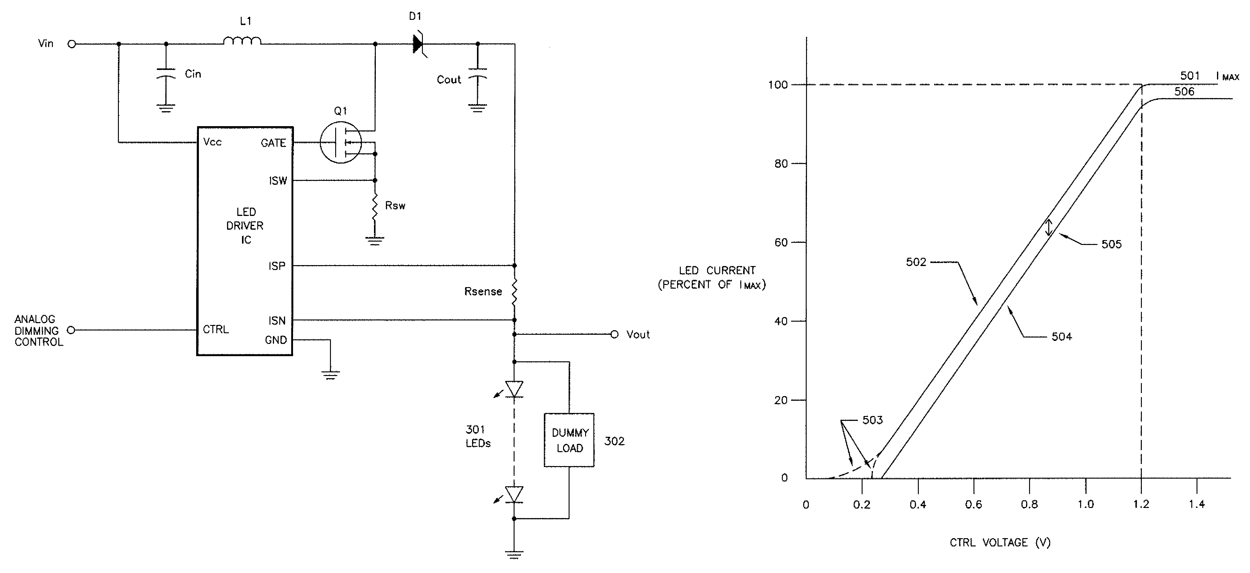
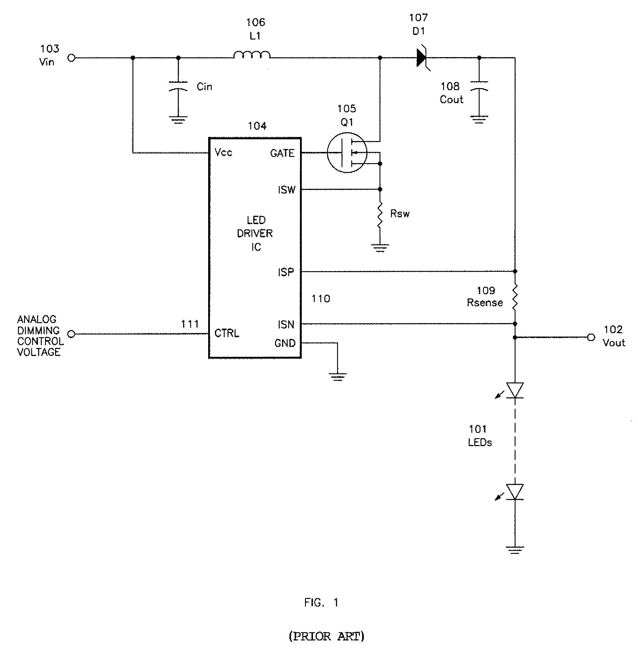
[0019]FIG. 1 illustrates a representative prior art LED illuminator design, with a string of LEDs (101) being driven by an LED driver circuit that is designed to provide a regulated, constant current. The LEDs (101) are connected in series, to ensure that the current is identical in each of the LED devices. The constant-current design is relatively insensitive to the number of LEDs in the string, as long as the total voltage drop across the string is lower the designed maximum output voltage of the driver circuit.

[0020]The prior art LED driver circuit shown in FIG. 1 is configured as a boost converter, in which the output voltage Vout (102) is intended to be a higher voltage than the input voltage Vin (103). LED driver circuits may also be configured as buck converter, with Vout designed to be a lower voltage than Vin, or as a buck-boost converter, in which Vout may be either higher or lower than Vin. One skilled in the art of LED driver circuit design will understand that the circu...


PUM


Abstract

By diverting a small amount of current from a string of LED(s) powered by a LED driver at low current levels in a process of dimming the LED string, performance of the LED string light emission is improved.

Description

CROSS-REFERENCE OF PATENT APPLICATION[0001]This application claims priority from U.S. Provisional Application No. 61 / 832,664, filed Jun. 7, 2013, which application is incorporated herein in its entirety by this reference.BACKGROUND[0002]This invention relates to a circuit design and associated method for implementing current-based analog dimming of Light Emitting Diode (LED) illuminators, and in particular to a circuit design and method that improves the performance and accuracy of the dimming function, at low levels of current through the LED devices.[0003]One of the basic required functions of the control circuits for LED illuminators is the ability to control the dimming or brightness of the LEDs. In most LED illuminator designs, direct current (DC) is fed through individual LED devices, or strings of LED devices, causing them to emit light. There are two basic methods of controlling the brightness of the LED devices, or dimming them. One of these basic methods is to vary the lev...

Claims


Application Information

Patent Timeline
Patent Type & Authority Patents(United States)
IPC IPC(8): H05B37/02H05B33/08H05B44/00
CPCH05B33/0806H05B45/10H05B45/3575H05B45/38H05B45/375H05B45/3725
Inventor CHEN, KUAN-POLEE, HO-SHANG
Owner DICON FIBEROPTICS
Why Eureka
Try Eureka