
Rotatable drive element for moving a window covering

a technology of rotating drive element and window covering, which is applied in the direction of curtain suspension device, door/window protective device, manufacturing tool, etc., can solve the problems of increasing assembly cost and adding complexity to the assembly

Active Publication Date: 2015-08-04
CURRENT PROD CORP
View PDF30 Cites 17 Cited by
  • Summary
  • Abstract
  • Description
  • Claims
  • Application Information

AI Technical Summary

Benefits of technology

The solution simplifies the window covering system by reducing components, allowing for independent operation and simultaneous positioning of multiple curtains, thereby reducing complexity and cost while enhancing user control over light and privacy.

Problems solved by technology

In these cases, the number of components used adds complexity to the assembly and also increases the cost of the assembly.

Method used


Image

  • Rotatable drive element for moving a window covering
  • Rotatable drive element for moving a window covering
  • Rotatable drive element for moving a window covering

Examples


Embodiment Construction

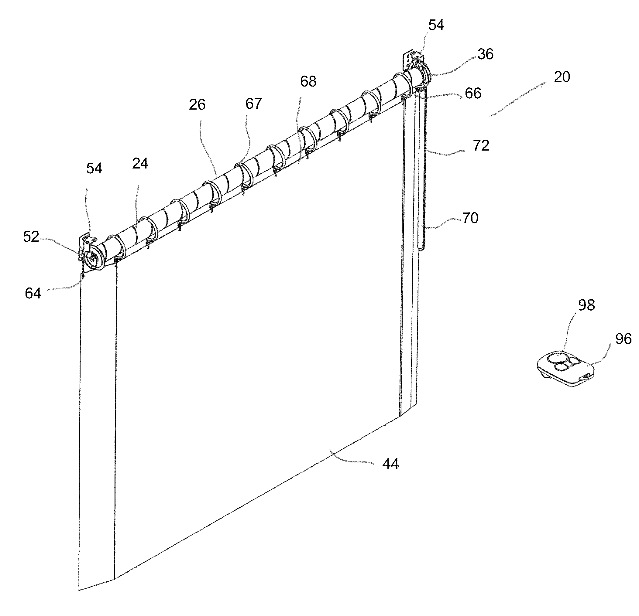
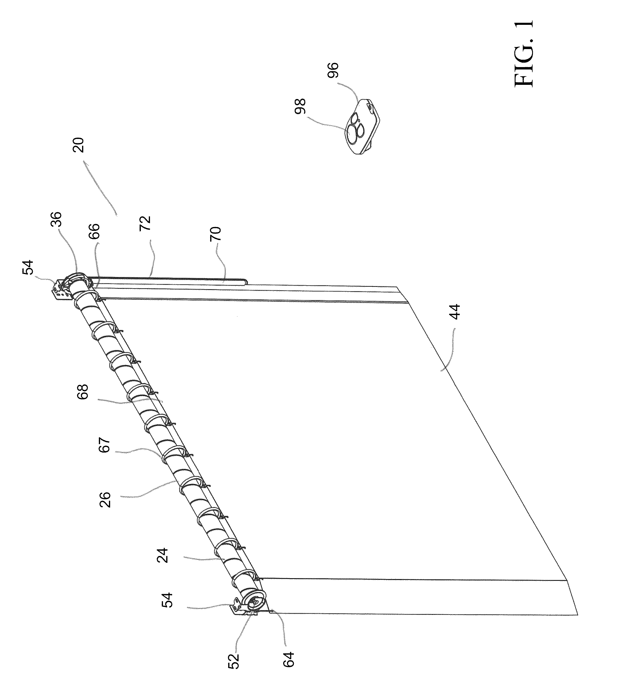
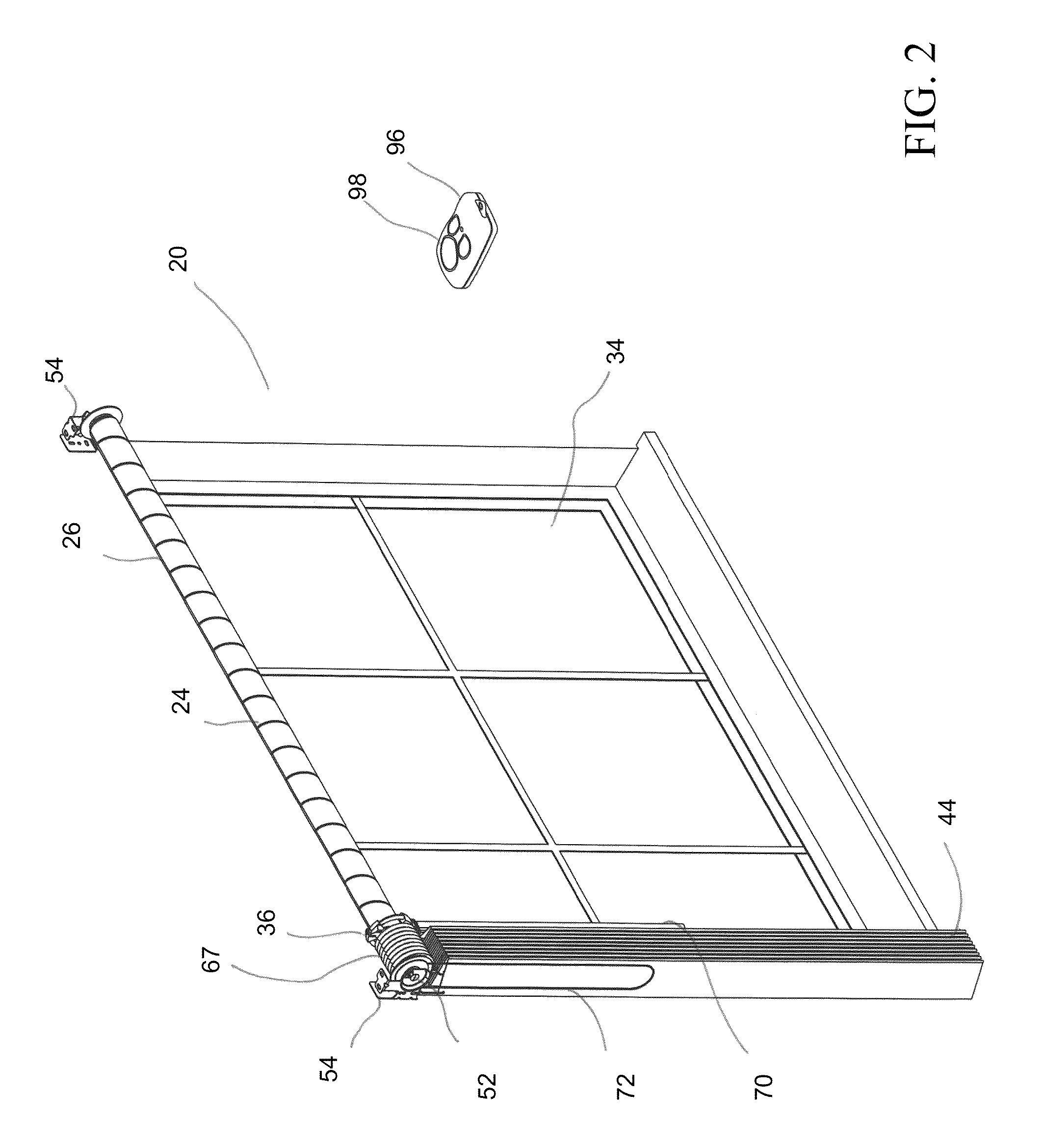
[0082]Referring to FIG. 1, a curtain assembly 20 according to one embodiment of the invention is shown. The curtain assembly 20 comprises a rotatable drive element 22 wherein a helical guide structure 24 is formed into the outer surface 26 of the drive element 22, a drive attachment element 36 having a corresponding structure 62 that communicates with the helical guide structure 24 to move the drive attachment element 36 axially along the drive element 22 when the drive element 22 is rotated and a rotation assembly 32 (not shown) for rotating the drive element 22. In some embodiments of the invention, the helical guide structure 24 is a helical groove 24 and the corresponding structure 62 is a tooth. While the helical guide structure 24 is shown in FIGS. 1-3 as a helical groove, the helical guide structure 24 is not limited to a groove. Similarly, the corresponding structure 36 discussed in the embodiments below is a tooth 62 but is not limited to being a tooth. In some embodiments,...


PUM

PropertyMeasurementUnit
outer diameteraaaaaaaaaa

Abstract

A curtain assembly comprises a rotatable drive element wherein at least one helical guide structure is formed on, or into, the outer surface of the drive element. A drive attachment element having a structure that communicates with the helical guide structure to move the drive attachment element axially along the drive element when the drive element is rotated. Specific embodiments incorporate either a manual or motor-driven rotation assembly for rotating the drive element. Further specific embodiments involve a helical guide structure that comprises a helical groove and a structure that comprises a tooth that engages with the helical groove.

Description

CROSS-REFERENCE TO RELATED APPLICATION[0001]The present application claims the benefit of U.S. Provisional Patent Application Ser. No. 61 / 702,093, filed Sep. 17, 2012, which is hereby incorporated by reference herein in its entirety, including any figures, tables, or drawings.FIELD OF THE INVENTION[0002]Embodiments of the present invention relate generally to a window covering assembly used to cover windows. Specific embodiments of the invention relate to a window covering assembly with a rotatable drive element that has a structure formed into or on the outer surface of the rotatable drive element such that a window covering moves axially along the rotatable drive element when the rotatable drive element rotates. Further specific embodiments relate to a window covering assembly in which two different curtains are operated by the same rotating drive element such that the user is able to independently move each curtain.BACKGROUND OF THE INVENTION[0003]Window coverings, such as curtai...

Claims


Application Information

Patent Timeline
Patent Type & Authority Patents(United States)
IPC IPC(8): A47H5/06B23B1/00A47H1/02B23Q1/76A47H23/00E06B9/72B23B5/08B23B3/00B23B29/26E06B9/40
CPCA47H1/02E06B9/72A47H5/06A47H23/00E06B9/40B23B1/00B23B29/26B23B3/00B23B5/08B23Q1/766B23B2260/024B23B2215/72B23B2220/12B23B2220/445Y10T82/10Y10T29/49826A47H13/02A47H2001/0215
Inventor MULLET, WILLIS JAYMATTHEWS, DANIEL T.FOX, MICHAEL D.
Owner CURRENT PROD CORP
Learn More