Biomass gasifier with disruption device

a gasifier and biomass technology, applied in the field of power generation systems, can solve the problems of not being able to detect the need of operator intervention, exposing the operator to higher than normal levels of reaction product gases, and fibrous biomass feedstock materials

Inactive Publication Date: 2015-08-04
AIR PROD & CHEM INC
View PDF26 Cites 1 Cited by
  • Summary
  • Abstract
  • Description
  • Claims
  • Application Information

AI Technical Summary

Problems solved by technology

Such biomass feedstock materials tend to be fibrous.
The need for operator intervention, however, may expose the operator to higher than normal levels of reaction product gases as well as exposure to the hot surfaces of the gasifier.
Moreover, the need of operator intervention generally is not detected until there is some degradation in the overall performance of the gasifier.

Method used


Image

  • Biomass gasifier with disruption device
  • Biomass gasifier with disruption device
  • Biomass gasifier with disruption device

Examples


Embodiment Construction

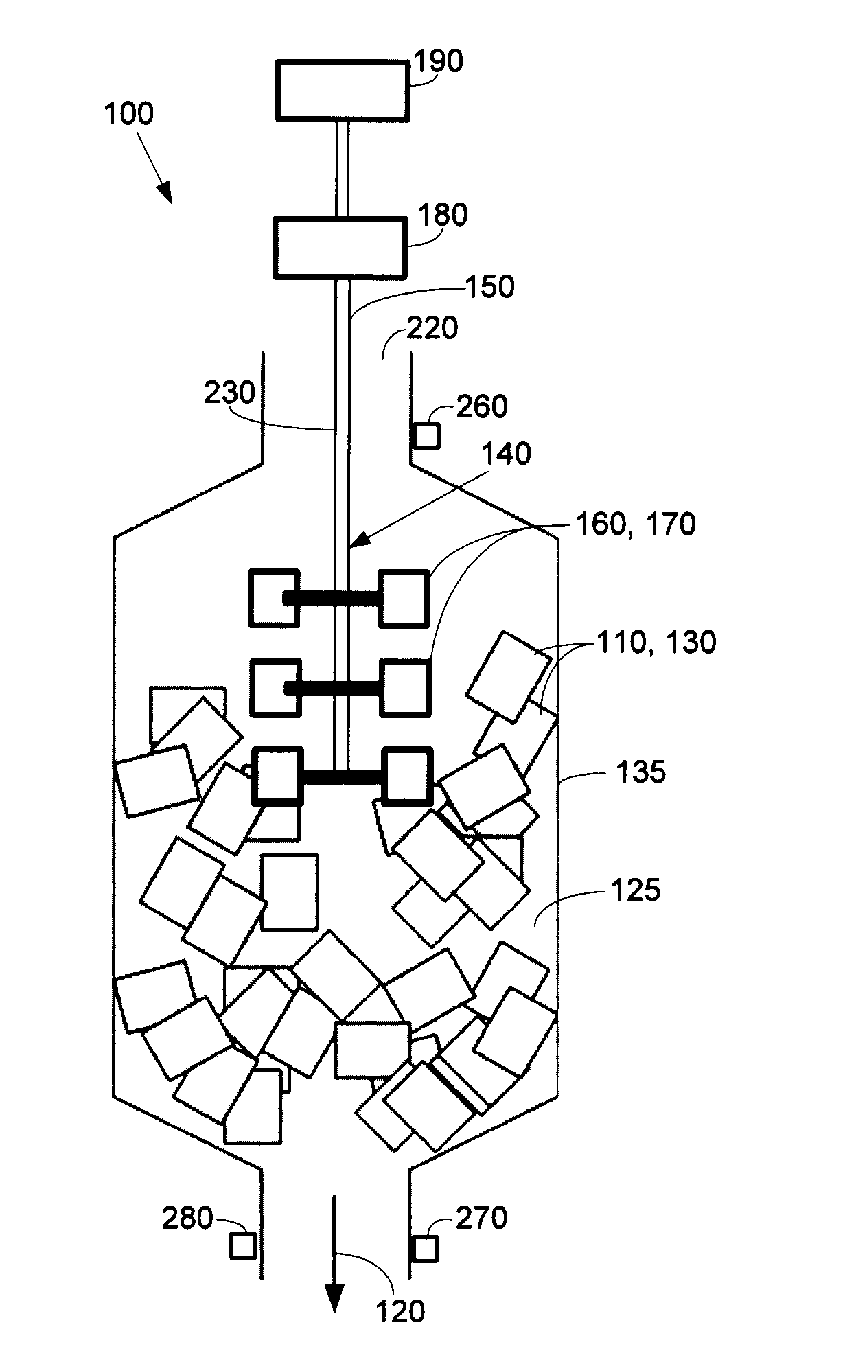
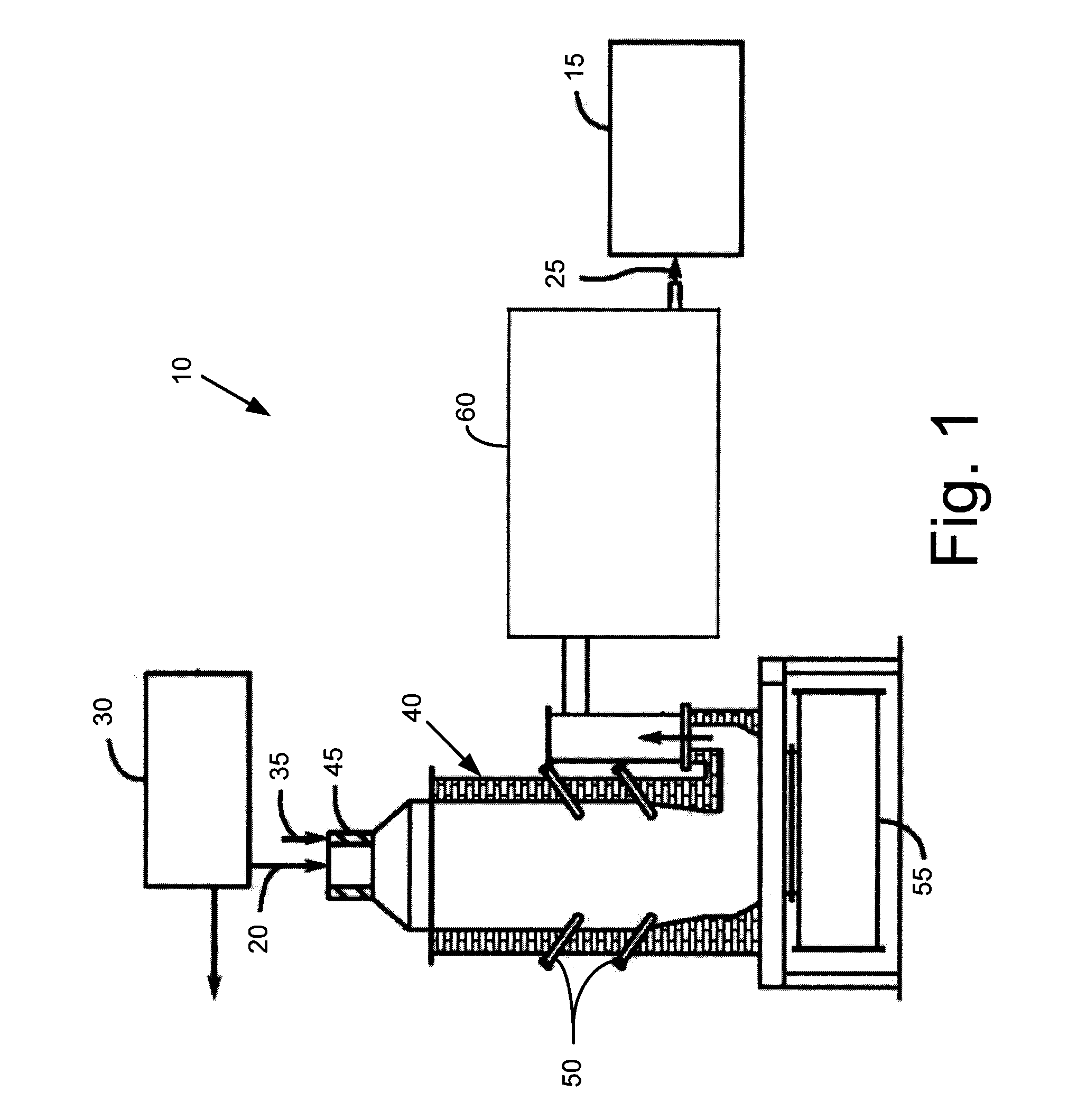
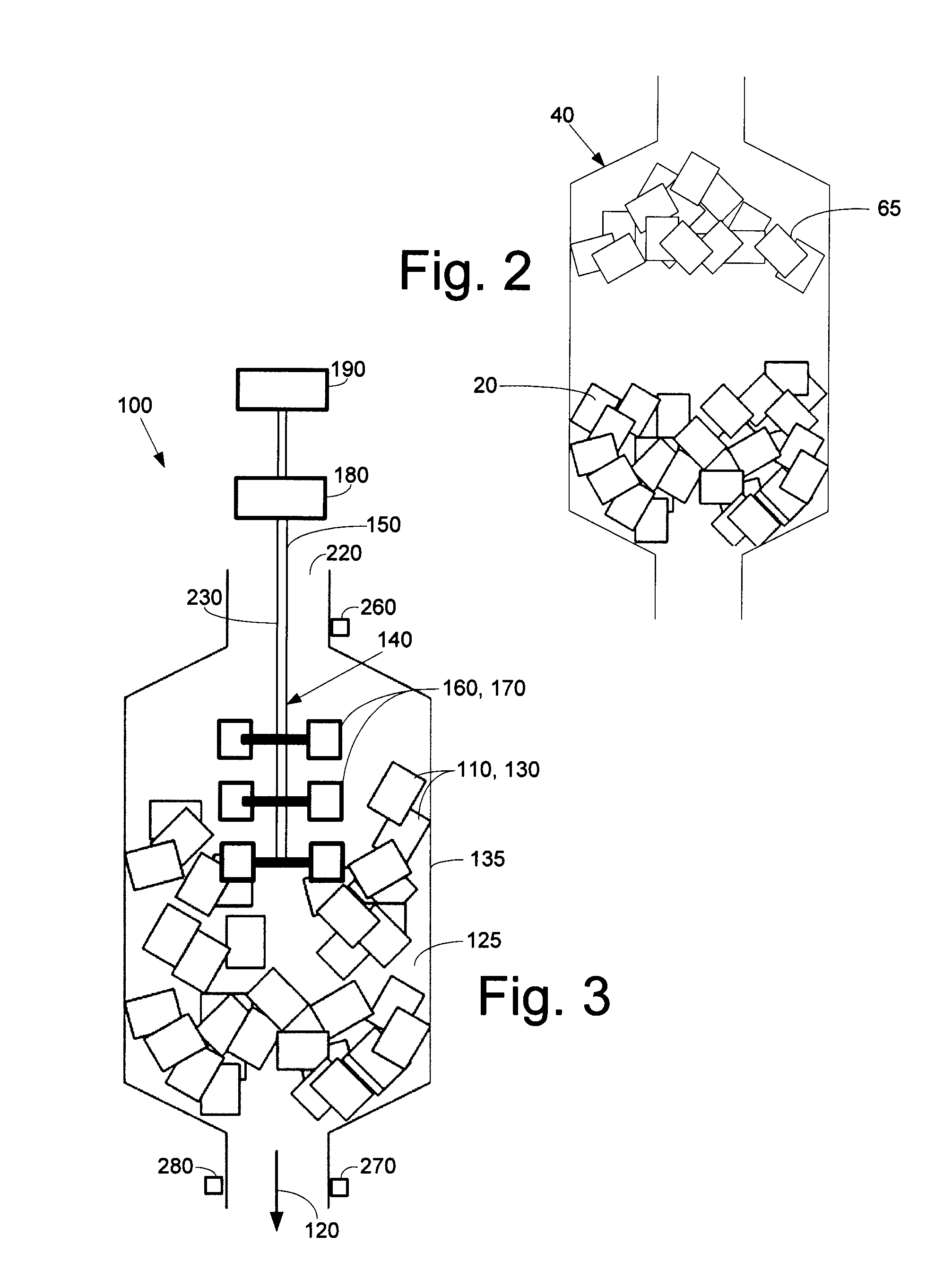
[0016]Referring now to the drawings, in which like numerals refer to like elements throughout the several views, FIG. 1 shows a schematic diagram of a biomass gasification system 10. Only a high level description of the components of the biomass gasification system 10 related to the subject matter described herein is shown for the purpose of simplification. One of ordinary skill in the art will understand that the overall biomass gasification system 10 may have other configurations and may use many other types of components. The biomass gasification system 10 may be integrated with a power generation system 15.

[0017]Generally described, the biomass gasification system 10 gasifies a biomass feedstock 20 to produce a treated producer gas 25. The producer gas 25 is a type of diluted syngas that may be produced by relatively low temperature gasification of biomass in the presence of air. The producer gas 25 may be directed to the power generation system 15 as a fuel source to generate p...


PUM

PropertyMeasurementUnit
pressureaaaaaaaaaa
flow rateaaaaaaaaaa
temperatureaaaaaaaaaa

Abstract

The present application thus provides a gasifier for use in converting a feedstock material into a syngas. The gasifier may include an outer chamber, a reaction zone positioned within the outer chamber, and a disruption device maneuverable within the outer chamber to ensure a steady flow of the feedstock material into the reaction zone without bridging.

Description

TECHNICAL FIELD[0001]The present application and the resultant patent relate generally to power generation systems and more particularly relate to a gasifier with an internal disruption device so as to prevent the bridging of biomass and other types of feedstock materials therein.BACKGROUND OF THE INVENTION[0002]In hydrocarbon gasification processes, solid fuels such as wood, agricultural wastes, and the like, are gasified to generate a gaseous fuel. Specifically, such gasification processes may convert a feedstock of biomass or other hydrocarbon into a gaseous mixture of carbon monoxide and hydrogen, i.e., a synthetic gas or a syngas referred to as a producer gas, by reaction with oxygen and steam in a gasifier. These gases then may be cleaned, processed, and utilized as a fuel in an engine to produce electricity. In other systems, the producer gas may be used to generate power, to produce fuel for heating, or to generate chemical products such as Fisher Tropsch liquids and the lik...

Claims


Application Information

Patent Timeline
Patent Type & Authority Patents(United States)
IPC IPC(8): B01J7/00C10J3/26C10J3/32
CPCC10J3/26C10J3/32C10J2300/165C10J2300/0906C10J2300/0916C10J2300/0956C10J3/30C10J2200/158C10J2200/36Y02P20/145Y02E20/18
Inventor DEPUY, RICHARD ANTHONYMAJMUDAR, JINMESH PRANAVMALL, OMPRAKASHVENKATRAMAN, VIGNESHDSOUZA, AVISH
Owner AIR PROD & CHEM INC
Why Eureka
Try Eureka