
Production of low sulfur syngas from natural gas with C4+/C5+ hydrocarbon recovery

a technology of hydrocarbon recovery and natural gas, which is applied in the direction of sulfur preparation/purification, hydrogen sulfides, and separation processes, etc., can solve the problems of loss of syngas productivity, low level, and easy poisoning of certain hcs catalysts and permanent deactivation

Inactive Publication Date: 2004-02-17
EXXON RES & ENG CO
View PDF40 Cites 125 Cited by
  • Summary
  • Abstract
  • Description
  • Claims
  • Application Information

AI Technical Summary

Benefits of technology

The invention relates to a process for producing low sulfur synthesis gas (syngas) from natural gas with C.sub.4+ / C.sub.5+ hydrocarbons recovery. The process involves treating the natural gas by amine scrubbing, low temperature hydrocarbon and sulfur separation, and contacting the resulting syngas with zinc oxide and nickel to reduce the sulfur content. The recovered hydrocarbons are then upgraded by hydrorefining and fractionation. The process produces a syngas feed with less than 10 vppb of sulfur, which increases the productivity of hydrocarbon synthesis and reduces catalyst deactivation in a fluid bed syngas generator.

Problems solved by technology

Sulfur in the feed to a syngas generator will poison the steam reforming catalyst and result in a loss of syngas productivity.
Certain HCS catalysts are easily poisoned and permanently deactivated by these sulfur bearing compounds.
Even levels as low as, for example, 10 vppb (volume parts per billion) are unacceptably high for a commercial HCS plant.
Consequently, the ability to achieve highly productive hydrocarbon synthesis with such catalysts, on a sustainable basis, has not yet been achieved.
When the sulfur content in natural gas fed into a FBSG containing a nickel reforming catalyst was reduced to less than 80 vppb, it resulted in less than a 1% per day activity loss.

Method used


Image

  • Production of low sulfur syngas from natural gas with C4+/C5+ hydrocarbon recovery
  • Production of low sulfur syngas from natural gas with C4+/C5+ hydrocarbon recovery

Examples


Embodiment Construction

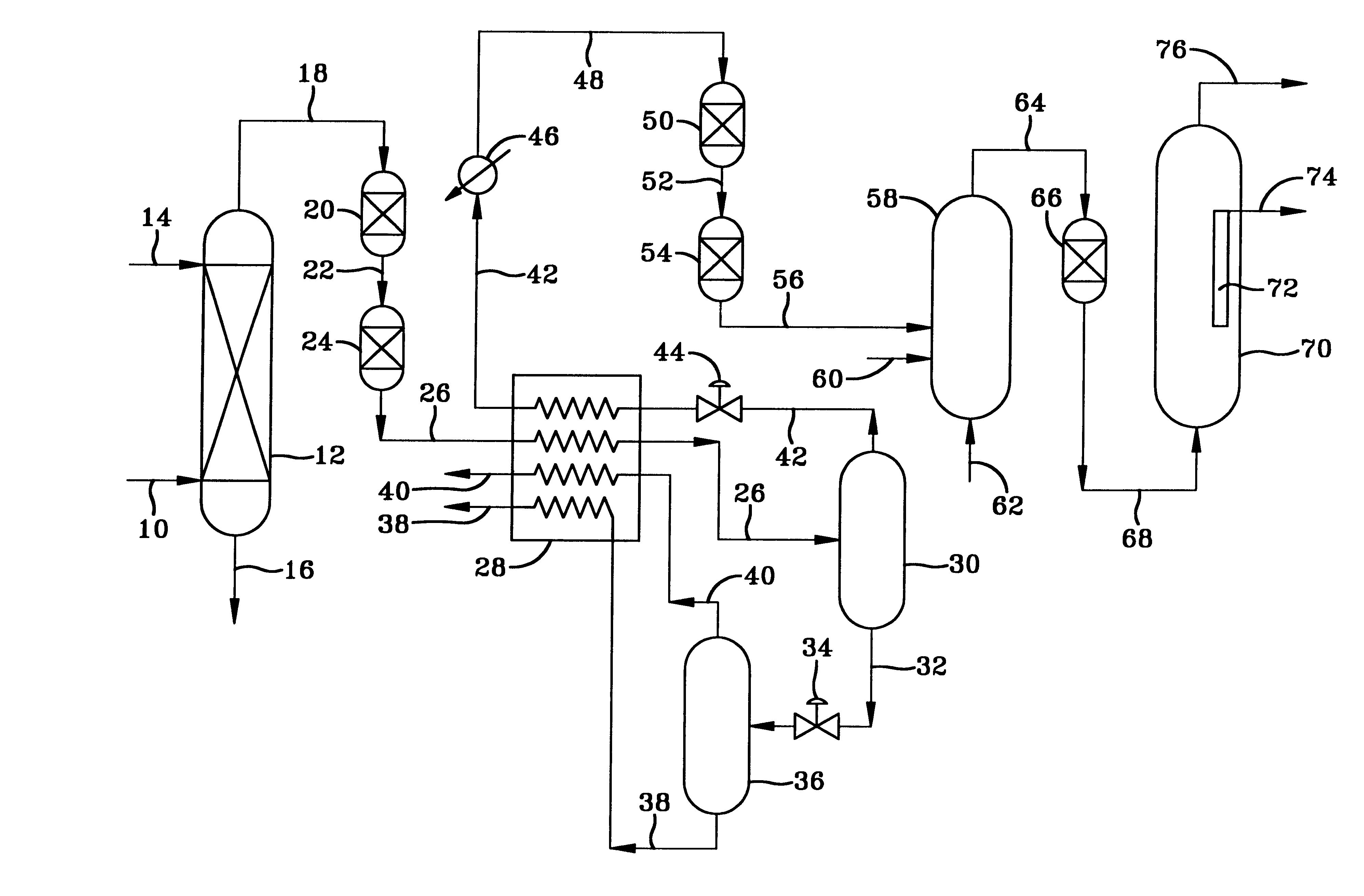
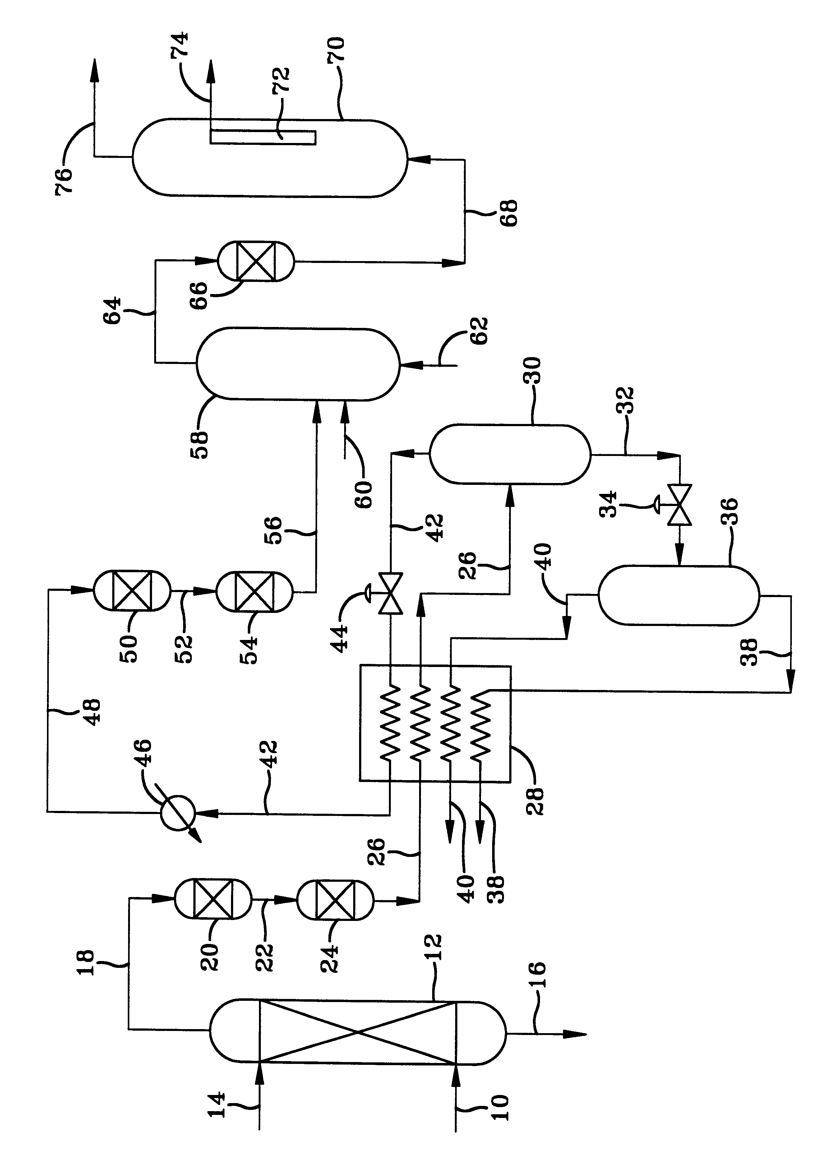
With specific reference to the FIGURE, natural gas at a pressure of about 1000 psig and a temperature of about 100.degree. F. is passed into a hindered amine treating unit 12 in which it contacts an aqueous solution of the amine. On a basis of 100.9 moles of gas per hour, the natural gas has a composition comprising 84.1 moles of methane, 5.6 moles of C.sub.2 hydrocarbons, 3.8 moles of nitrogen, 3.3 moles of C.sub.3+ hydrocarbons, 1.5 moles of C.sub.4+ hydrocarbons, 2.14 moles of CO.sub.2, 0.5 moles of H.sub.2 O, with the remainder H.sub.2 S and organic sulfur compounds of which over 95% is H.sub.2 S. The gas exiting the amine treating unit has less than 1000 vppm of CO.sub.2, about 1 vppm of H.sub.2 S and 1 vppm organic sulfur compounds. The gas is then passed into the adiabatic expansion cryogenic unit in which the expansion of the gas through one or more orifices cools the gas down to -30.degree. F. This causes the C.sub.4+ hydrocarbons and more of the sulfur to condense out of t...


PUM

PropertyMeasurementUnit
temperatureaaaaaaaaaa
half lifeaaaaaaaaaa
temperatureaaaaaaaaaa

Abstract

Sour natural gas is processed to remove the sulfur compounds and recover C4+ / C5+ hydrocarbons by scrubbing the gas with an amine solution to remove most of the sulfur, followed cooling the gas to remove C4+ / C5+ hydrocarbons and more sulfur compounds as liquid condensate to produce a gas having less than 20 vppm of total sulfur. The condensate is sent to a fractionator to recover the C4+ / C5+ hydrocarbons. The sulfur and hydrocarbon reduced gas is contacted first with zinc oxide and then nickel, to produce a gas having less than 10 vppb of total sulfur which is passed into a synthesis gas generating unit to form a very low sulfur synthesis gas comprising a mixture of H2 and CO. This synthesis gas is useful for hydrocarbon synthesis with increased life of the hydrocarbon synthesis catalyst and greater hydrocarbon production from the hydrocarbon synthesis reactor. Contacting the synthesis gas with zinc oxide further reduces the sulfur content to below 3 vppb.

Description

1. Field of the InventionThe invention relates to a process for producing low sulfur synthesis gas (syngas) from natural gas with C.sub.4+ / C.sub.5+ hydrocarbon recovery. More particularly the invention relates to producing very low sulfur syngas from sour natural gas with C.sub.4+ / C.sub.5+ hydrocarbon recovery and to the use of the syngas for hydrocarbon synthesis. The sulfur content of the syngas is less than 10 vppb and preferably less than 3 vppb. The process includes treating the natural gas by amine scrubbing, low temperature hydrocarbon and sulfur separation, followed by contact with zinc oxide and then nickel.2. Background of the InventionHydrocarbon synthesis (HCS) processes are well known and include fixed bed, fluid bed and slurry type processes in which a synthesis gas (syngas) comprising a mixture of H.sub.2 and CO is reacted in the presence of a suitable Fischer-Tropsch type of hydrocarbon synthesis catalyst at conditions effective to form hydrocarbons, and preferably...

Claims


Application Information

Patent Timeline
Patent Type & Authority Patents(United States)
IPC IPC(8): B01D53/48B01D53/04B01D53/52C10L3/10C10L3/00B01D53/14
CPCB01D53/04B01D53/48B01D53/52C10L3/10B01D2253/112B01D2256/16B01D2256/20B01D2256/24B01D2257/30B01D2257/304B01D2257/306B01D2257/308B01D2258/06B01D2259/402
Inventor ALEXION, DENNIS G.FEDICH, ROBERT B.WILBUR, JOHN C.TAYLOR, JR., JAMES H.GLASS, JR., JAMES P.SAY, GEOFFREY R.O'CONNOR, RICHARD P.
Owner EXXON RES & ENG CO
Learn More