Pressure reducer for a device for enriching a liquid with carbon dioxide

a technology of carbon dioxide and reducer, which is applied in the direction of valve housings, fluid pressure control, instruments, etc., can solve the problems of short service life of valves and the sacrifice of cost savings achieved by using plastic to produce housings, and achieve the effect of reducing costs

Inactive Publication Date: 2015-08-04
LUXEMBOURG PATENT CO SA
View PDF15 Cites 0 Cited by
  • Summary
  • Abstract
  • Description
  • Claims
  • Application Information

AI Technical Summary

Benefits of technology

[0008]The disclosure proposes an improved development of a pressure reducer which permits less costly production while ensuring the least possible reduction in quality and safety of the pressure reducer.
[0013]Using a valve housing made of plastic, in particular in one piece from injection molded plastic, enables significant cost savings. The special insert constitutes the functionally relevant sealing or seating surface on the high-pressure side which is exposed to elevated loads. Thanks to the insert taking the form of a separately made part, said surface may be produced in the insert inexpensively and with high precision.
[0014]In a first development of the invention, the insert may for example be made of metal, in particular of brass. In this development, the annular shoulder surface, which interacts as the seating surface with the first seal on the control body, is formed in the metal. As a consequence, the reliability and quality of a pressure reducer made in the conventional manner, i.e. with an all-metal housing, are substantially achieved.
[0016]It should be noted that, on the low-pressure side, the housing plastic may straightforwardly form the sealing surface for the surface sealed by the second seal on the actuating piston, since substantially lower loads prevail on the low-pressure side and any potential leakage is of lesser concern here. The actuating piston itself may also be made of plastic, so reducing costs.

Problems solved by technology

One drawback of plastic is in principle the short service life of the valve on exposure to severe loads.
However, this has the drawback that any cost savings which might be achieved by using plastic to produce the housing must be partially or entirely sacrificed at least in part due to the necessary metal coating and the associated additional plant and equipment and method steps.

Method used


Image

  • Pressure reducer for a device for enriching a liquid with carbon dioxide
  • Pressure reducer for a device for enriching a liquid with carbon dioxide
  • Pressure reducer for a device for enriching a liquid with carbon dioxide

Examples


Embodiment Construction

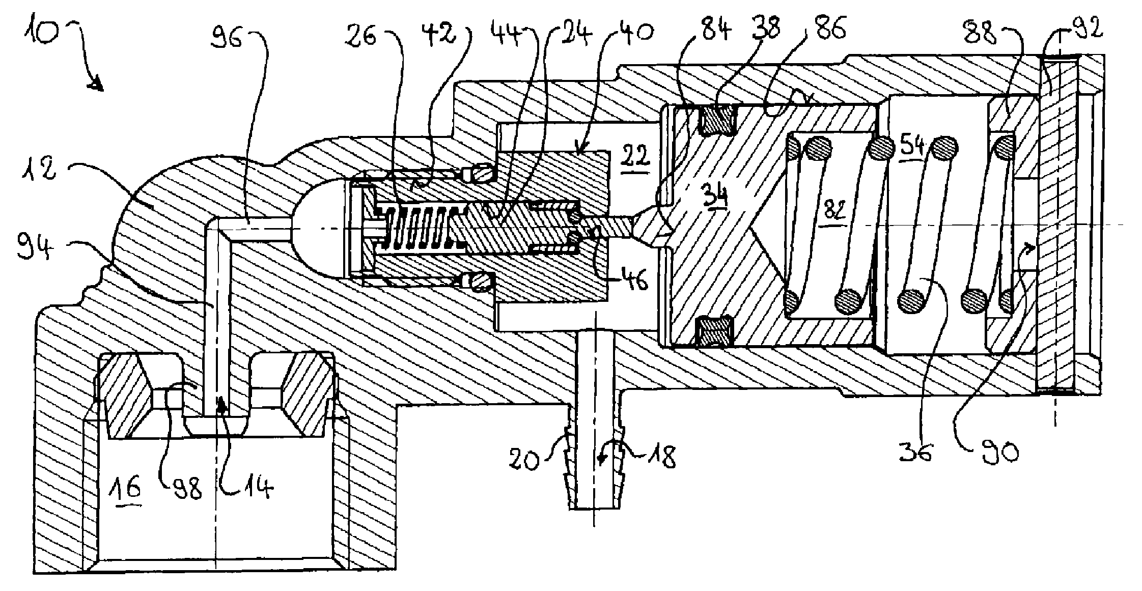
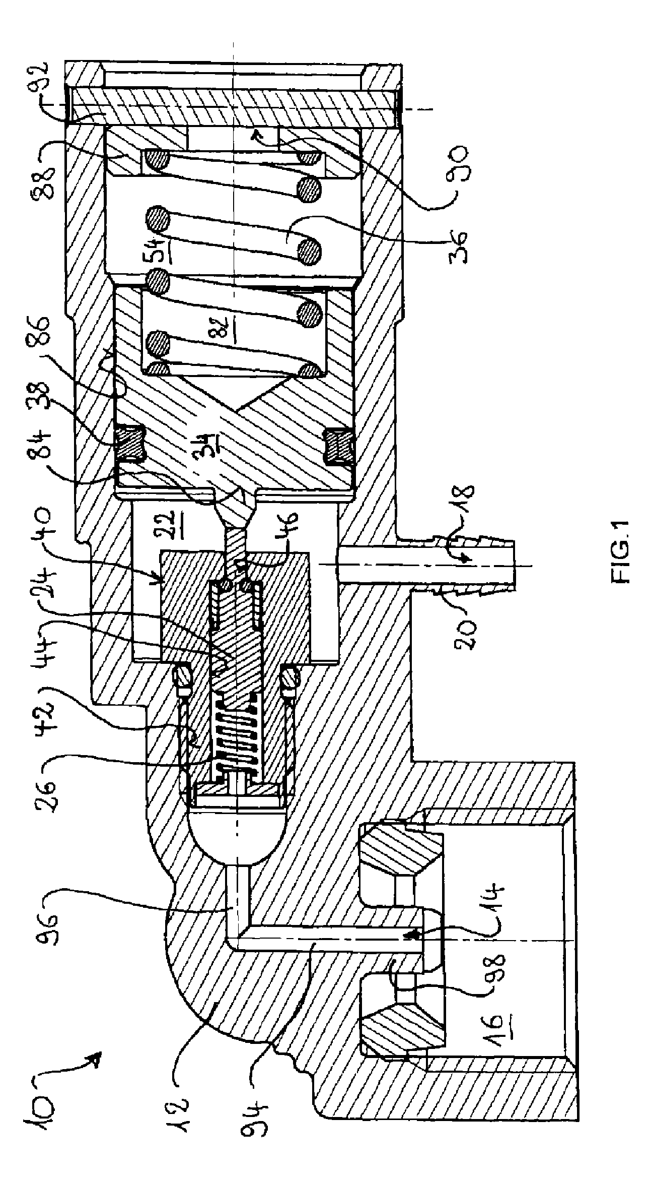
[0022]FIG. 1 shows a pressure reducer 10 in a central longitudinal section through its housing 12. The pressure reducer 10 was specially developed for use in a device for enriching a liquid with gas, in particular for enriching drinking water with carbon dioxide, as disclosed for example in WO 2009 / 021960.

[0023]The structure of the pressure reducer 10 will first be described. The housing 12 has an inlet 14 with associated inlet port 16 for connecting the pressure reducer 10 to a gas vessel, for example a CO2 cartridge or cylinder. The inlet port 16 may take the form of a threaded bush of metal, not shown in greater detail, inserted into the housing 12 as an axial extension around the inlet 14, which bush is for example screwed together with a carbon dioxide gas vessel. In a preferred embodiment, the inlet port 16 takes the form of an internal thread formed in one piece with the housing 12. The housing 12 furthermore has an outlet 18 with associated outlet port 20 for connecting the ...


PUM


Abstract

A pressure reducer includes a housing with an axially displaceable biased control body in order to close a connection between an inlet and an expansion chamber, where the housing is equipped with an axially displaceable biased actuating piston in order to displace the control body against the spring load of the control body as a function of the pressure in the expansion chamber and to open the connection, the housing being made of plastic, and the pressure reducer includes a separately made insert, where the insert is fixed between the inlet and the expansion chamber in the plastic housing and said insert has a guide bore, which is connected to the inlet and supports the control body, and a connecting bore, which adjoins the guide bore and which opens into the expansion chamber, where the insert forms an annular shoulder surface between the connecting bore and the guide bore, said shoulder surface interacting as a seating surface with the seal on the control body.

Description

TECHNICAL FIELD[0001]The present invention relates in general to a pressure reducer (also known as a pressure-reducing valve, pressure reduction valve or reducing valve) and specifically to a pressure reducer for use as a component of a device for enriching a liquid with gas, in particular for enriching drinking water with carbon dioxide.BRIEF DISCUSSION OF RELATED ART[0002]Devices for enriching beverages, in particular drinking water, with gas, in particular with carbon dioxide (also known as the carbonation of drinking water) have long been known. Drinking water is usually carbonated in a storage tank. Devices have recently been developed for enriching tap water with carbon dioxide using a “continuous flow method”. Such devices are particularly suitable for use in domestic applications or in bars / restaurants. In the continuous flow method without a storage tank, carbonation proceeds in a continuous flow mixer which is directly connected to the drinking water pipe. In comparison wi...

Claims


Application Information

Patent Timeline
Patent Type & Authority Patents(United States)
IPC IPC(8): F16K31/12G05D16/10G05D16/00F16K1/30F16K27/02
CPCF16K1/307F16K27/02G05D16/10G05D16/00Y10T137/7793G05D16/107
Inventor BORMES, SASCHA
Owner LUXEMBOURG PATENT CO SA
Why Eureka
Try Eureka