Method of calibrating a slicer in a receiver or the like

a technology of slicer and receiver, applied in the field of receivers, can solve the problems of reducing the overall receiver performance, affecting the accuracy of the overall receiver, so as to reduce the offset error

Inactive Publication Date: 2015-08-04
AVAGO TECH INT SALES PTE LTD
View PDF9 Cites 4 Cited by
  • Summary
  • Abstract
  • Description
  • Claims
  • Application Information

AI Technical Summary

Benefits of technology

[0007]In one embodiment of the invention, a method is described for reducing offset errors in a data slicer having at least two analog inputs and a digital output. A fixed signal is applied to a first one of the data slicer inputs, the fixed signal having a known value. Then a calibration signal is applied to a second one of the data slicer inputs, the calibration signal having a first starting value. The value of the calibration signal is changed by an amount having a first polarity until the output of the data slicer changes state. Once the output changes state, the value of the calibration signal is stored as a first value. Then the value of the calibration signal is set to a second starting value different from the first starting value and the calibration signal value is changed by a second amount having a second polarity opposite the first polarity until the output of the data slicer changes state. Once the output changes state, the value of the calibration signal is averaged with stored value to form a calibration signal average value and the calibration signal average value is applied as the calibration signal to the data slicer input. Then the fixed signal from the data slicer input is removed and an input signal is applied to the data slicer input.

Problems solved by technology

Signals arriving at a receiver are typically corrupted by intersymbol interference (ISI), crosstalk, echo, and other noise.
However, these receivers are sensitive to offset-induced slicing errors where the slicing threshold determines whether received signal is a one or a zero.
Because the amplitude of the received signals is around one hundred millivolts, an offset-induced slicing voltage error of tens of millivolts is a relatively large percentage of the signal amplitude and can seriously degrade performance of the overall receiver.

Method used


Image

  • Method of calibrating a slicer in a receiver or the like
  • Method of calibrating a slicer in a receiver or the like
  • Method of calibrating a slicer in a receiver or the like

Examples


Embodiment Construction

[0014]Reference herein to “one embodiment” or “an embodiment” means that a particular feature, structure, or characteristic described in connection with the embodiment can be included in at least one embodiment of the invention. The appearances of the phrase “in one embodiment” in various places in the specification are not necessarily all referring to the same embodiment, nor are separate or alternative embodiments necessarily mutually exclusive of other embodiments. The same applies to the term “implementation”.

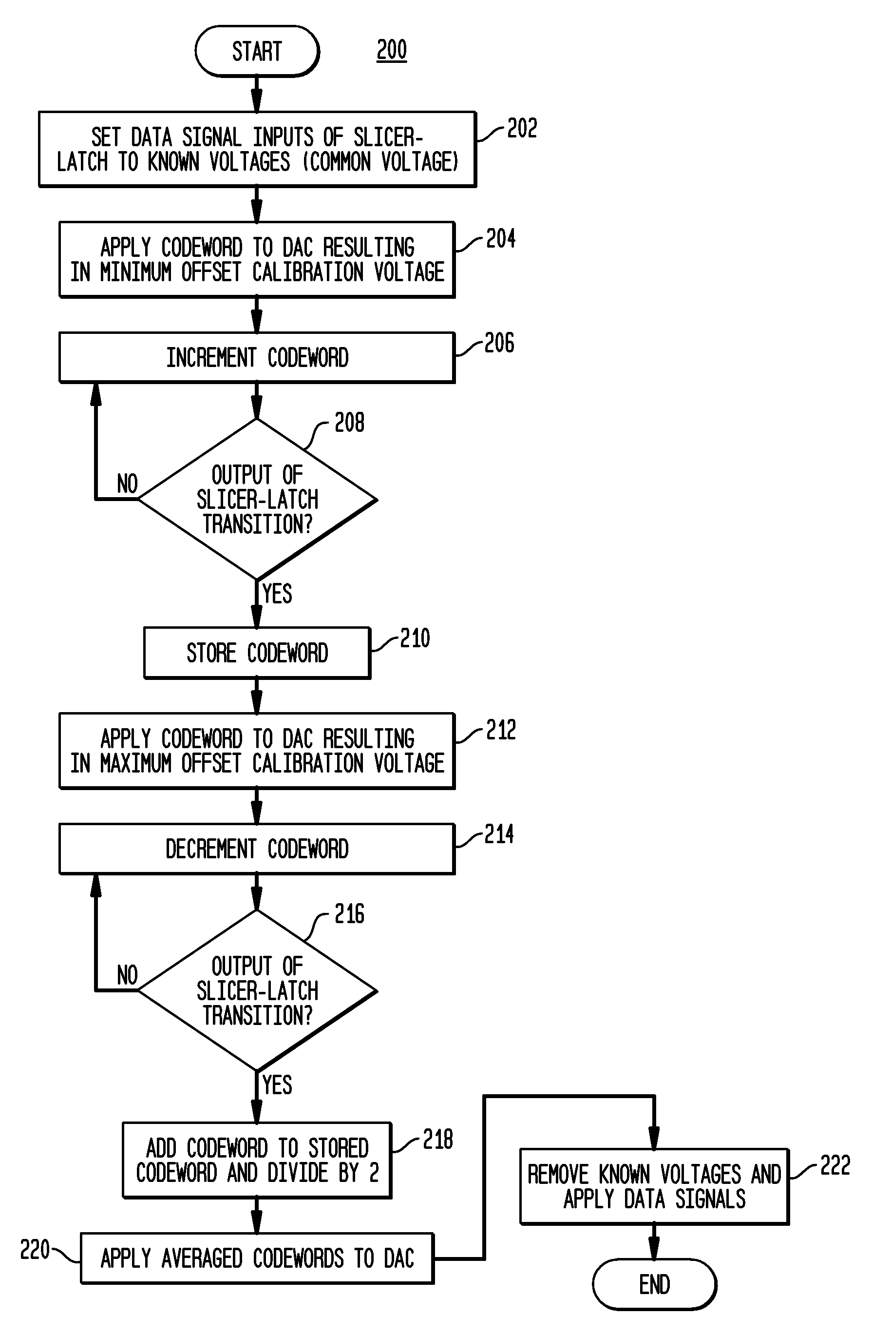
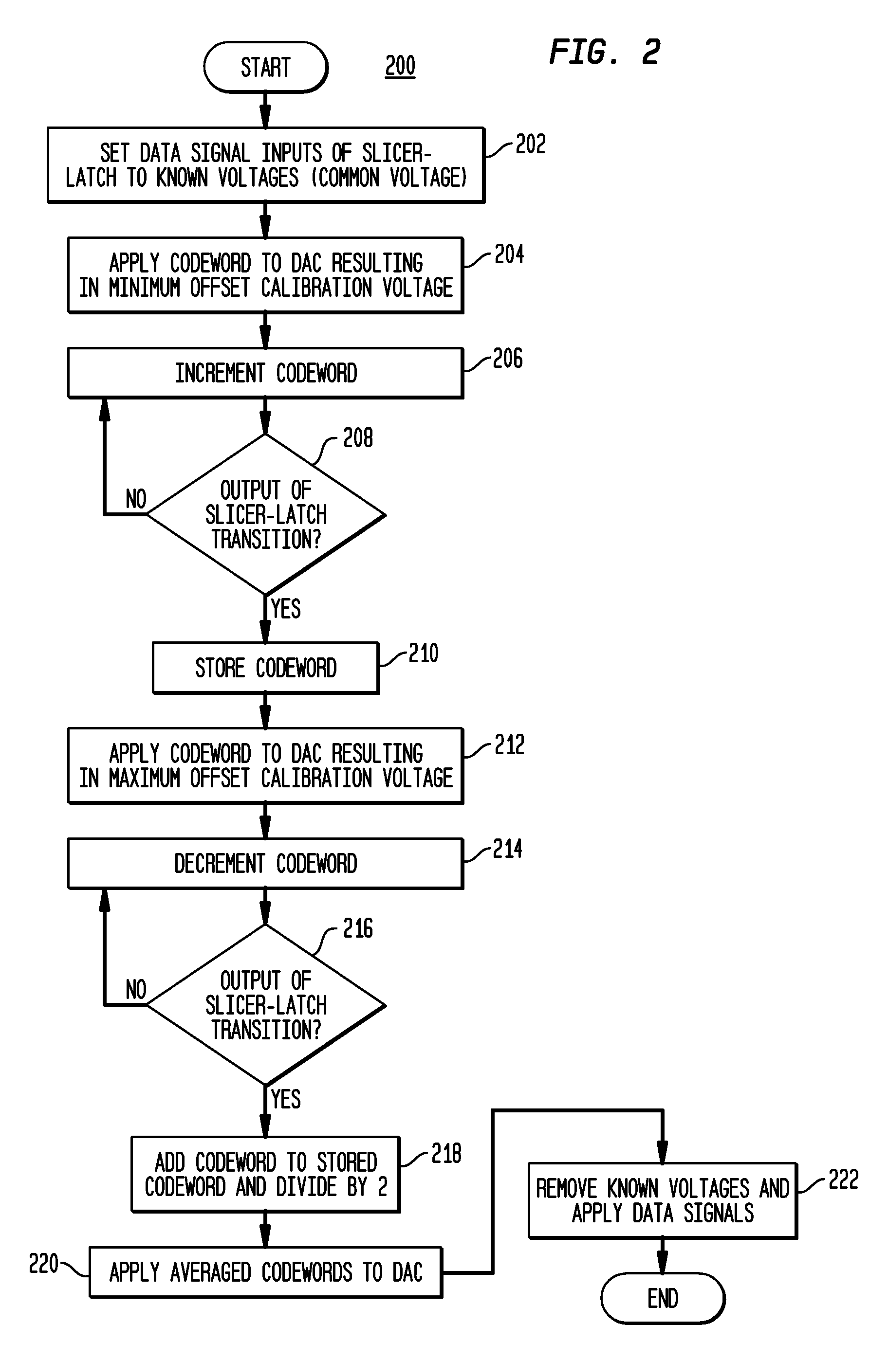
[0015]It should be understood that the steps of the exemplary methods set forth herein are not necessarily required to be performed in the order described, and the order of the steps of such methods should be understood to be merely exemplary. Likewise, additional steps might be included in such methods, and certain steps might be omitted or combined, in methods consistent with various embodiments of the present invention.

[0016]Also for purposes of this description, the ter...


PUM


Abstract

A method of calibrating data slicer-latches in a receiver to remove offset errors in the slicer-latches. A known voltage is applied to all but one of the inputs of the slicer-latch. The remaining input receives an offset cancelation voltage from a DAC is stepped upward from a minimum voltage until the slicer-latch output transitions by incrementing a codeword to the DAC and the codeword that resulted the transition is saved. Then the offset cancelation voltage is swept downward in steps from a maximum voltage until the slicer-latch output transitions and the codeword that caused the transition is averaged with the stored codeword. The average of the codewords is applied to the DAC to generate the offset cancelation voltage used during normal operation of the receiver.

Description

BACKGROUND[0001]1. Field of the Invention[0002]The present invention relates to receivers generally and, more specifically, to calibration of the slicers in the receiver to remove offset errors therein.[0003]2. Description of the Related Art[0004]Communication receivers that recover digital signals must sample an analog waveform and then reliably detect the sampled data. Signals arriving at a receiver are typically corrupted by intersymbol interference (ISI), crosstalk, echo, and other noise. As data rates increase, the receiver must both equalize the channel, to compensate for such corruptions, and detect the encoded signals at increasingly higher clock rates. Decision-feedback equalization (DFE) is a widely used technique for removing intersymbol interference and other noise at high data rates.[0005]Generally, decision-feedback equalization utilizes a nonlinear equalizer to equalize the channel using a feedback loop based on previously detected (or decided) data. In one typical DF...

Claims


Application Information

Patent Timeline
Patent Type & Authority Patents(United States)
IPC IPC(8): H04L25/06H04L25/03
CPCH04L25/03057H04L25/063H04L2025/03789
Inventor JING, TAIGAO, HAIRONG
Owner AVAGO TECH INT SALES PTE LTD
Why Eureka
Try Eureka