Steerable suture instrument

a technology of surgical sutures and instruments, applied in the field of surgical sutures, can solve the problems of long recovery period, difficult to achieve using a rigid and straight instrument, and risk of permanent injury to surrounding tissues, and achieve the effect of prolonging the recovery period

Inactive Publication Date: 2015-08-11
JORDAN CHRISTOPHER S
View PDF17 Cites 5 Cited by
  • Summary
  • Abstract
  • Description
  • Claims
  • Application Information

AI Technical Summary

Benefits of technology

[0013]During a surgical procedure, surgical instruments comprising a handle and shaft portion and an application end are used by surgeons. These include cutting tools, suture passers, probes, grasping tools and clamps, among several. The insertion of these instruments is accomplished by either the tool cutting its own pathway, or the tools being inserted through a hole that is already cut through the tissue to the site of the surgical procedure. Quite often, this pathway is not a straight line, having the pathway directed around certain tissues as opposed to through them. This is difficult to accomplish using a rigid and straight instrument. Where the entry is made with a rigid instrument, more extensive damage is done to the surrounding tissue leading to a longer period of recovery and the risk of permanent injury to the surrounding tissues.
[0014]In some case, surgical instruments do include a curved portion at or near an end, or at least include an angled application end. However, the pathway of these surgical instruments are restricted to the pathway being cut along the predetermined curved portion. Often tissue is unnecessarily damaged, stretched or displaced along the pathway due to having to insert and remove the surgical instrument to achieve the direction and angle desired to reach the site of the surgery from the external insertion point. It would be more suitable and less damaging to the collateral tissue if the surgeon had the ability to steer the surgical instrument, reducing the destruction of collateral tissue along the pathway, and actually have the ability to direct the surgical instrument at any desired angle or curve and in more than one direction.
[0015]It is one of several objectives to provide a surgical instrument having an intentionally directed steerable operational end to reduce the amount of tissue damage during the insertion and use of the surgical instrument and the attached tool. It would also be an objective to provide the surgical instrument with the ability to be steered in tow opposite directions under the direct control of the surgeon, using a single finger or thumb movement during the operation with the same hand used to grasp the instrument, manipulate the degree and direction of the bend of the operational end, and to guide the surgical instrument within the location of surgery intended by the surgeon with a reduction in the amount of damage to any collateral tissue at the surgical site. It is yet another objective to make the instrument in a simple, inexpensive and sanitary conscious manner where the instrument is cheap to manufacture, easy to assembly and easy to clean after use, with the handle, extension tub and pin made of metal with smooth surfaces with little if any obscured areas making them easy to clean, and the shaped inner member made of plastic, nylon or other moldable and resilient material which is cheap enough to provide and manufacture that it can simply be disposed of after use.

Problems solved by technology

This is difficult to accomplish using a rigid and straight instrument.
Where the entry is made with a rigid instrument, more extensive damage is done to the surrounding tissue leading to a longer period of recovery and the risk of permanent injury to the surrounding tissues.
However, the pathway of these surgical instruments are restricted to the pathway being cut along the predetermined curved portion.
Often tissue is unnecessarily damaged, stretched or displaced along the pathway due to having to insert and remove the surgical instrument to achieve the direction and angle desired to reach the site of the surgery from the external insertion point.

Method used


Image

  • Steerable suture instrument
  • Steerable suture instrument
  • Steerable suture instrument

Examples


Embodiment Construction

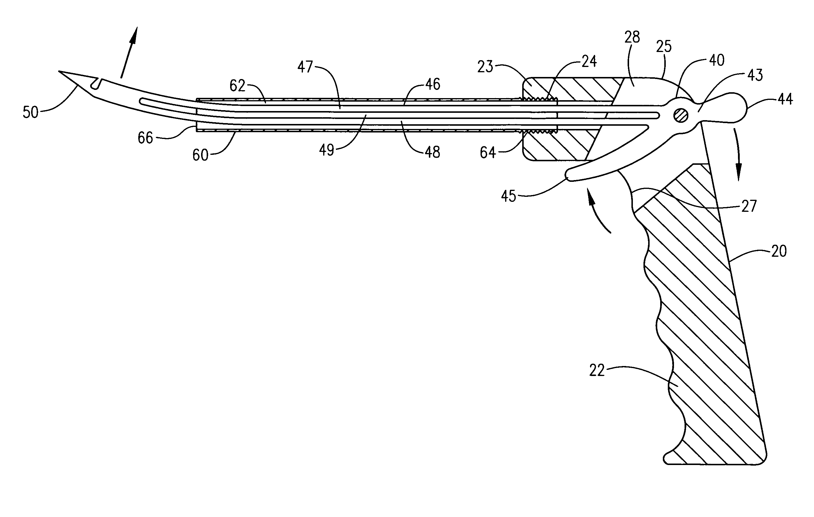
[0025]A single hand held and operational surgical instrument having a steerable, bi-directionally active capability is disclosed allowing a surgeon to insert the operation end 50 or instrument tip through soft tissue in a non-linear pathway, reducing the amount of damage to collateral tissues during the course of the surgical procedure. The instrument may be presented in any number of embodiments having a variety of surgical penetrating instruments formed or attached to an operational end of the instrument, but for purposes of the present disclosed embodiment, the operational end 50 is a suture passer instrument.

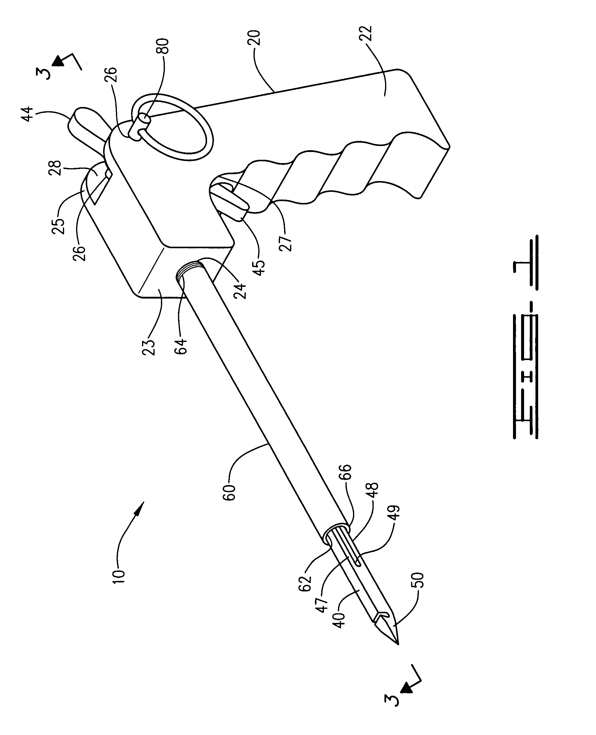
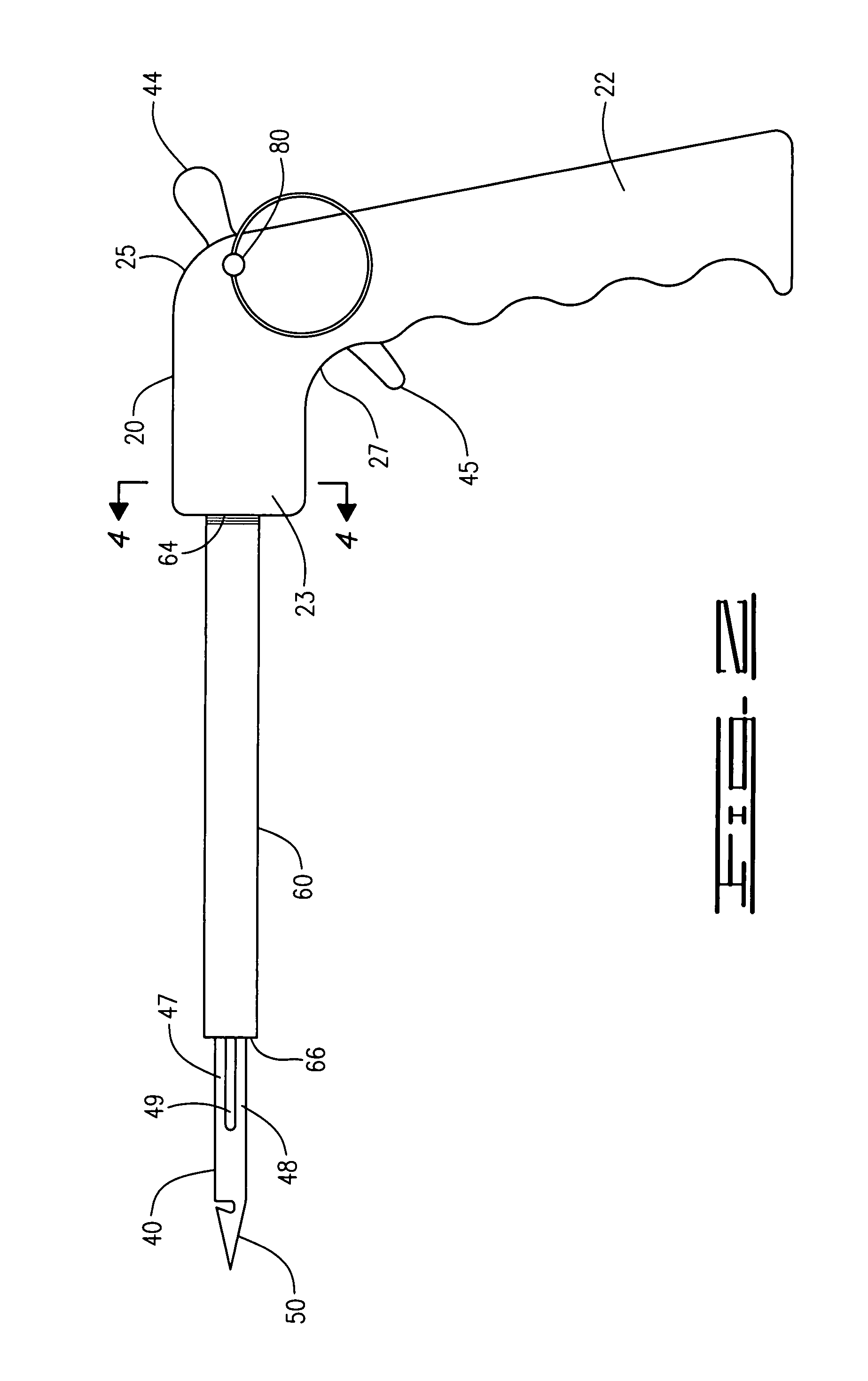
[0026]Thus, the steerable surgical instrument 10, as represented and illustrated in FIGS. 1-7B of the drawings, defines a simple assembly of four components, including a handle 20, a resilient transactional member 40, an extension tube 60 and lock pin 80 which may be readily joined and assembled and disassembled for application and for cleaning, with the transactional member...


PUM


Abstract

A steerable surgical suture passer providing single hand operation to selectively direct the operation tip in an upward or downward direction to reduce the degree of collateral tissue damage during the use of the instrument, the suture passer providing a shaped handle for ambidextrous use and defining an inner socket, an integrated inner member defining an upper trigger and lower trigger at a proximal end, a pair of resilient intermediate parallel shaft members and a distal operational tip, the inner member pivotally secured within the inner socket by a single pin and a rigid hollow shaft support tube connected to the handle through which the resilient parallel shaft members are directed, allowing the surgeon to steer the operations tip and required when performing a surgical procedure.

Description

CROSS REFERENCE TO RELATED APPLICATIONS[0001]None.I. BACKGROUND OF THE INVENTION[0002]1. Field of Invention[0003]A steerable surgical suture passer providing single hand operation to selectively direct the operation tip in an upward or downward direction to reduce the degree of collateral tissue damage during the use of the instrument, the suture passer providing a shaped handle for ambidextrous use and defining an inner socket, an integrated inner member defining an upper trigger and lower trigger at a proximal end, a pair of resilient intermediate parallel shaft members and a distal operational tip, the inner member pivotally secured within the inner socket by a single pin and a rigid hollow shaft support tube connected to the handle through which the resilient parallel shaft members are directed, allowing the surgeon to steer the operations tip and required when performing a surgical procedure.[0004]2. Description of Prior Art[0005]The following U.S. patents and publications were...

Claims


Application Information

Patent Timeline
Patent Type & Authority Patents(United States)
IPC IPC(8): A61B17/04
CPCA61B17/0469A61B2017/00318A61B2017/06042A61B2017/06095
Inventor JORDAN, CHRISTOPHER S.
Owner JORDAN CHRISTOPHER S
Why Eureka
Try Eureka