Printing apparatus

a printing apparatus and printing technology, applied in the field of printing apparatuses, can solve the problems of franking strip, inability to achieve the effect of reducing the deflection of the brush body, and reducing the efficiency of the brush element, so as to improve the transport function of such a printing apparatus, without negatively affecting the transport and printing

Active Publication Date: 2015-08-11
FRANCOTYP POSTALIA
View PDF5 Cites 0 Cited by
  • Summary
  • Abstract
  • Description
  • Claims
  • Application Information

AI Technical Summary

Benefits of technology

[0010]There is a need to improve the transport function of such a printing apparatus for strip-shaped printing substrates in a simple manner without negatively affecting the transport and the printing of flat items other than the strip-shaped substrates. A printing apparatus should be equipped to transport strip-shaped printing substrates so as to ensure that the strip-shaped printing substrates are transported without slippage due to pressure triggering and during the printing.
[0014]In a second variant, the separate contact pressure element is already pivoted by the control unit due to a kinematic coupling of mechanical components of the printing apparatus and of the box-shaped module when said box-shaped module is inserted into the printing apparatus. A roller borne so as to be rotationally movable on an axle is used in order to avoid an unnecessary friction of the separately movable contact pressure element and of the transport belt of a transport device.

Problems solved by technology

The spring elements of the additional spring system are likewise compression springs, but with a spring constant that is larger than that of the compression springs of the first spring system, such that at F1opt=F3min, the brush elements for the deflection of the brush body are increasingly ineffective counter to the spring force, because the resilience due to the spring elements of the additional spring system is transitioned into a force range as of F3min.
However, a disadvantage can occur in the event that a very thin flat good (such as a franking strip) should be transported further via the transport belt.
A disadvantage of this solution is the engagement of a strip-shaped printing substrate (franking strip) only in the border region, wherein a printing takes place in a wider printing region of the strip-shaped printing substrate.
By interaction with the adjustably set force effect of the spring force in the range F2min to F2max, the narrower border region of the franking strip can have a disadvantageous effect on the setting of a slip-free transport, so that an offset of the imprint appears in the print image.

Method used


Image

  • Printing apparatus
  • Printing apparatus
  • Printing apparatus

Examples


Embodiment Construction

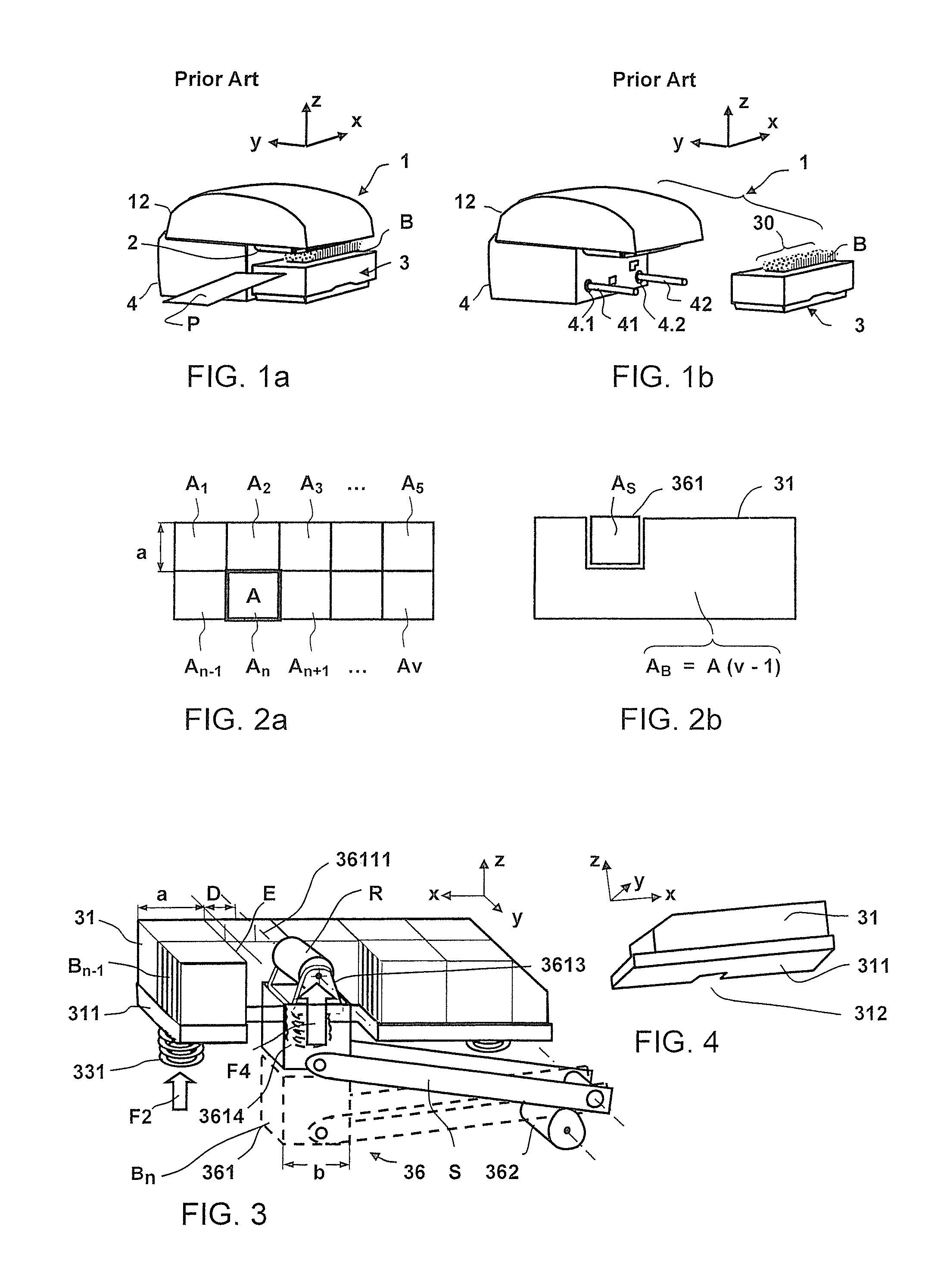
[0034]FIG. 1a shows a perspective view of a printing apparatus 1 from the front upper left, with an inserted box-shaped module 3 that is docked at a lower housing shell 4 below an upper housing shell 12, and in which contact pressure elements B are provided in order to press a flat good P from below onto a transport belt 2 arranged in the upper housing shell 12. The contact pressure elements are designed in the form of a brush. An arrow that designates the x-direction of a Cartesian coordinate system points in the transport direction for a flat good. The insertion direction of the box-shaped module is identified by an arrow in the y-direction, and the contact pressure due to the contact pressure elements takes place in the z-direction of the Cartesian coordinate system. This coordinate system is also retained in the following.

[0035]FIG. 1b shows a perspective view of a printing apparatus 1 from the front upper left with a removed box-shaped module 3. Two guide elements 41 and 42 tha...


PUM


Abstract

A printing apparatus has an ink printing device onto which a flat item being transported om the x-direction for printing thereon is pressed by a contact pressure device, wherein the base of the contact pressure device has a contact pressure body floor plate biased by a spring force. A notch at the edge of the contact pressure body floor plate extends further in the contact pressure body in the z-direction, up to the ink printing device. An additional contact pressure device for strip-shaped printing substrates has a contact pressure element designed so as to be movable separate from the contact pressure body, and biased with a spring force of an additional spring or resiliently elastic element. The contact pressure element is arranged so as to be movable in the notch. A sensor for print triggering is arranged at a front wall of a lower housing shell of the printing apparatus and has a sensor region that is adjacent to the separate contact pressure element in the insertion direction y of a box-shaped module.

Description

BACKGROUND OF THE INVENTION[0001]1. Field of the Invention[0002]The invention concerns a printing apparatus of the type having a separate contact pressure element for franking strips. Such a printing apparatus has a removable, box-shaped module at the lower part of a housing and a transport device with a transport belt in the upper part of a housing, wherein mail pieces are transported in a gap between the two parts. The printing apparatus is connected with mail processing apparatuses, in particular for use in a franking machine.[0003]2. Description of the Prior Art[0004]As used herein, a mail piece is a printing substrate such as a letter or a small width, elongated length printing substrate such as franking strips, or another flat good that has three dimensions and that is suitable for receiving print indicia.[0005]A printing apparatus of modular design with a removable, box-shaped module is known from German Utility Patent DE 202010015354 U1, in which contact pressure elements ar...

Claims


Application Information

Patent Timeline
Patent Type & Authority Patents(United States)
IPC IPC(8): B41J15/00B41J2/045
CPCB41J11/0095B41J13/12B41J29/02B41J29/13B41J2/04501G07B17/00508G07B2017/00532G07B2017/00556G07B2017/00233G07B2017/00241G07B2017/0062
Inventor BECKMANN, STEFANMUHL, WOLFGANG
Owner FRANCOTYP POSTALIA
Why Eureka
Try Eureka