Electrowetting display device

a display device and display screen technology, applied in the field of electrowetting display devices, can solve the problems of difficult control of injection and reduced amount of opaque oil filled into the unit pixel, and achieve the effect of high display quality

Inactive Publication Date: 2015-08-11
LIQUAVISTA BV
View PDF8 Cites 0 Cited by
  • Summary
  • Abstract
  • Description
  • Claims
  • Application Information

AI Technical Summary

Benefits of technology

[0009]Exemplary embodiments of the present invention provide an electrowetting display device capable of realizing a high display quality.
[0010]Exemplary embodiments of the present invention also provide an electrowetting display device capable of increasing a display capacity.
[0036]An electrowetting display device according to an exemplary embodiment of the present invention, one main pixel configured by plural pixel electrodes is formed. A common notch electrode is formed. An amount of an opaque oil injected into the main pixel may be controlled to realize a high display quality.
[0037]Moreover, a partition wall within a main pixel is removed and an opaque oil is gathered into a single area, so that a non-transmitting area may be reduced to increase a transmissivity.
[0038]Moreover, a utilizability of a non-transmitting area may be increased and a configuration of a color filter may be arranged so that a tranamittivity per a unit pixel may be increased.

Problems solved by technology

In a display device having a high display quality, as a size of a unit pixel is decreased, an amount of opaque oil filled into the unit pixel is reduced so that it is difficult to control injection.

Method used


Image

  • Electrowetting display device
  • Electrowetting display device
  • Electrowetting display device

Examples


Embodiment Construction

[0051]Hereinafter, exemplary embodiments of the present invention will be explained in detail with reference to the accompanying drawings.

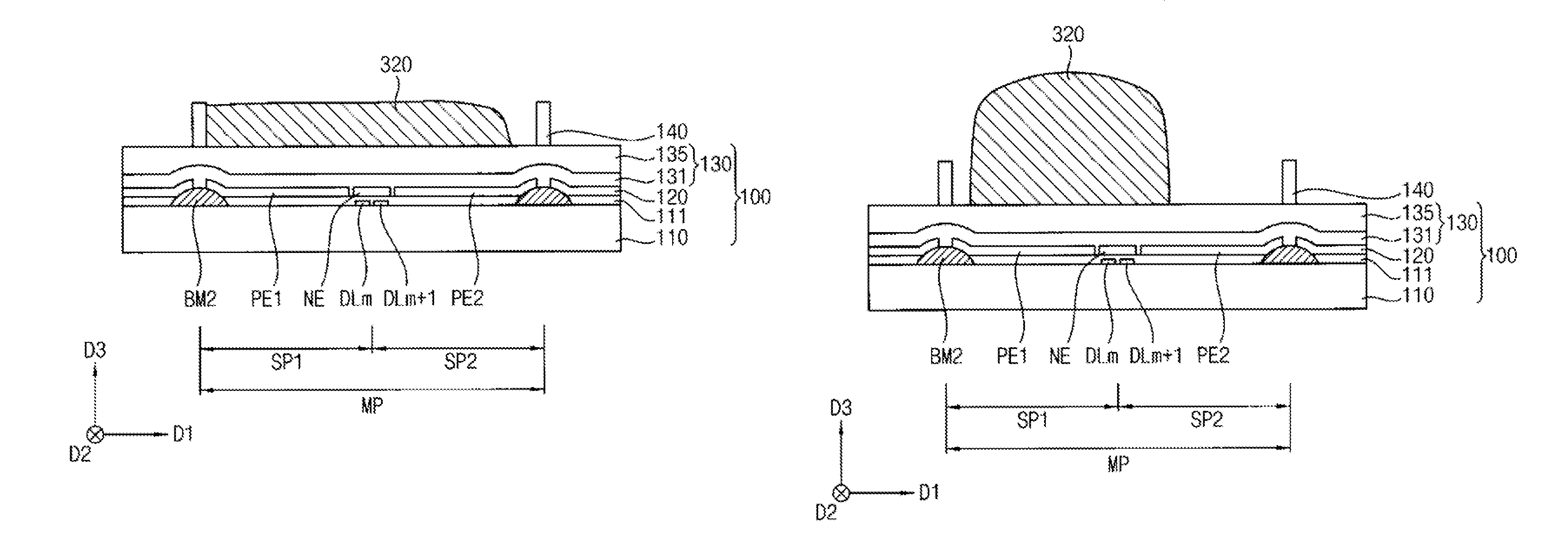
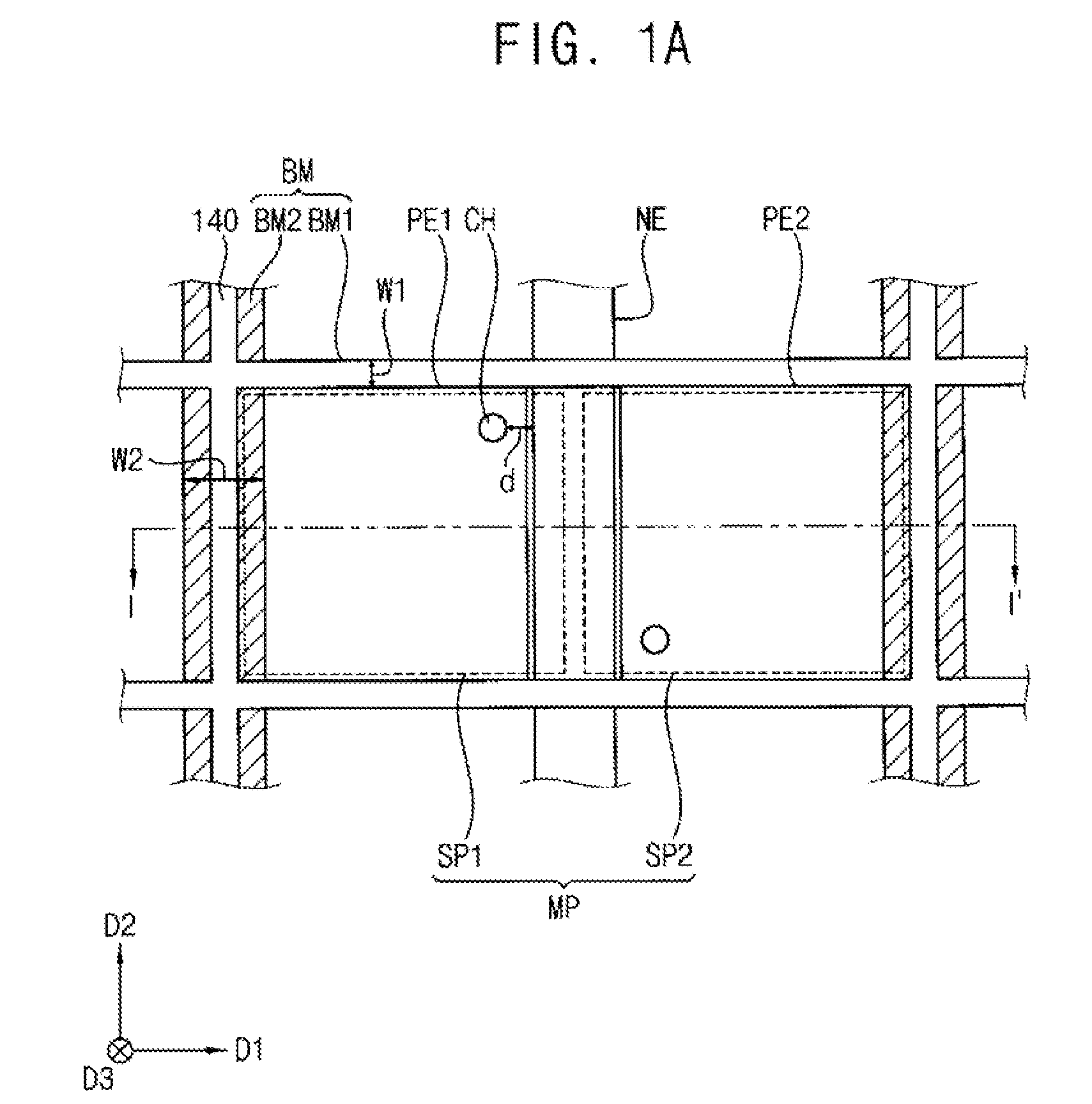
[0052]FIGS. 1A and 1B are plan views illustrating an electrowetting display device according to an exemplary embodiment of the present invention. FIG. 2 is a cross-sectional view taken along a line I-I′ of FIG. 1A.

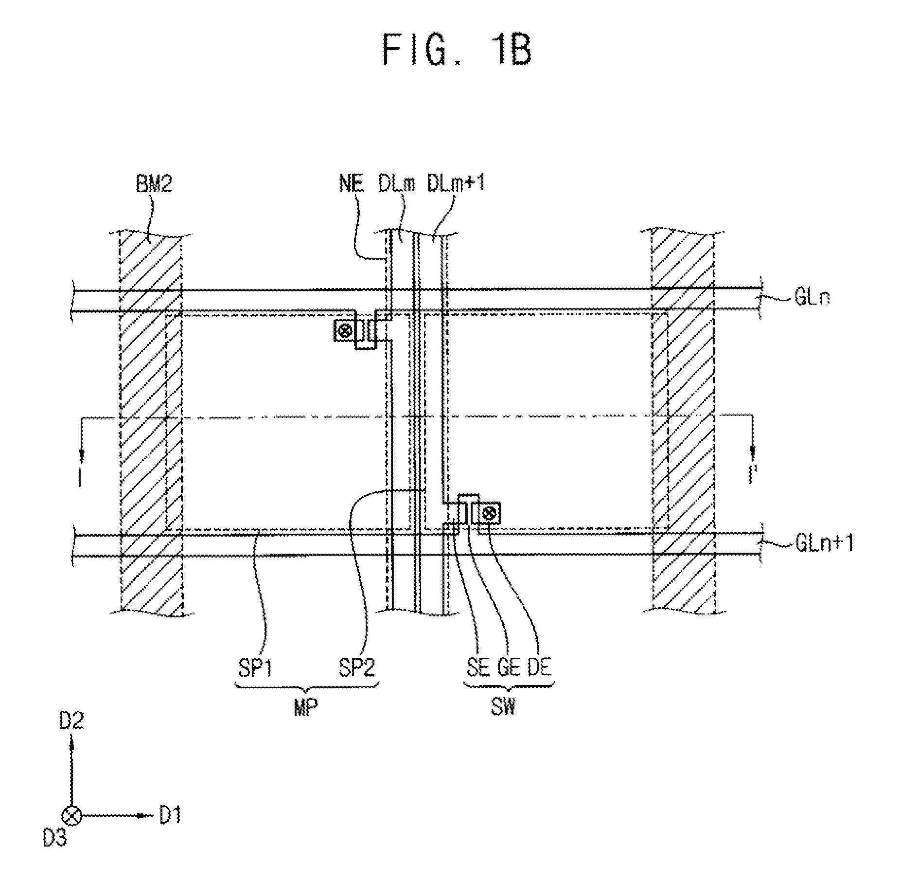
[0053]FIG. 1A is a plan view illustrating a main pixel including plural pixel electrodes and a common notch electrode. FIG. 1B is a plan view illustrating a switching element, gate lines, and data lines that are formed on a first base substrate.

[0054]Referring to FIGS. 1A, 1B, and 2, an electrowetting display device 10 according to an exemplary embodiment of the present invention includes a first substrate 100, a second substrate 200 opposite to the first substrate 100, a conductive fluid 310 disposed between the first and second substrates 100 and 200 and a non-conductive fluid 320 disposed between the first and second substrates 100 an...


PUM


Abstract

An electrowetting display device includes a first substrate, a second substrate, a conductive fluid and a non-conductive fluid. The first substrate includes a first base substrate, a first electrode layer, a hydrophobic insulation layer and a partition wall. The first electrode layer is formed on the first base substrate and includes pixel electrodes spaced apart from each other and a common notch electrode formed between the pixel electrodes. The hydrophobic insulation layer is formed on the first electrode layer. The partition wall is formed surrounding the pixel electrodes and the common notch electrode on the hydrophobic insulation layer. The second substrate is opposite to the first substrate. The conductive fluid and the non-conductive fluid are interposed between the first and second substrates. The conductive fluid and the non-conductive fluid are controlled to vary transmittance of light in accordance with an electric signal applied to the pixel electrodes.

Description

CROSS-REFERENCE TO RELATED APPLICATIONS[0001]This application claims priority under 35 U.S.C. §119 to Korean Patent Application No. 10-2012-0027195, filed on Mar. 16, 2012 in the Korean Intellectual Property Office (KIPO), the contents of which are herein incorporated by reference in their entirety.TECHNICAL FIELD[0002]Exemplary embodiments of the present invention relate to an electrowetting display device. More particularly, exemplary embodiments of the present invention relate to an electrowetting display device that controls a transmissivity of light.DISCUSSION OF THE RELATED ART[0003]An electrowetting display device includes a conductive fluid and a non-conductive fluid to display an image by varying a surface tension of the conductive fluid in accordance with a voltage. As the electrowetting display device does not have a polarization plate, flexibility or transmissivity may be increased in comparison with a liquid crystal display device. Moreover, the electrowetting display d...

Claims


Application Information

Patent Timeline
Patent Type & Authority Patents(United States)
IPC IPC(8): G02B26/00
CPCG02B26/005G02B2207/115
Inventor CHO, HYEON-GUKIM, SANG-ILBAEK, SEUNG-JINCHOI, JIN-WOO
Owner LIQUAVISTA BV
Why Eureka
Try Eureka