Torsion bar spring arrangement for a wheel suspension of a motor vehicle

a technology for torsion bars and motor vehicles, which is applied in the direction of vehicle springs, resilient suspensions, interconnection systems, etc., can solve the problems of disproportionate stress, reduced working capacity of torsion bars, and increased stress simultaneously, so as to simplify the design of the motor uni

Inactive Publication Date: 2015-08-18
AUDI AG
View PDF48 Cites 17 Cited by
  • Summary
  • Abstract
  • Description
  • Claims
  • Application Information

AI Technical Summary

Benefits of technology

[0007]According to the invention, it is proposed that the housing of the actuator is no longer rigidly mounted on the vehicle body without having a resilient property, but is mounted resiliently yielding at a body-side bearing point of the vehicle with a defined spring rate. In this way, a resilient component is connected upstream in series with the torsion bar spring in a simple manner, or superimposed, which lowers the spring rate of the spring arrangement and reduces the torsional loads on the torsion bar springs.
[0009]According to another advantageous feature of the present invention, the motor-gear unit may be mounted at the bearing point on the vehicle body so as to be movably in the circumferential direction and may be supported on the vehicle body by at least one spring element in the direction of the torsion moments acting on the rotary bar springs. This proposed arrangement quasi divides the torsion bar spring arrangement into the torsion bar and the additional spring element, namely with an interposed motor-gear unit. The motor-gear unit produces the variable pre-tension in a conventional manner, whereas the torsional moment is supported by the output lever and the torsion bar spring is supported on the actuator unit and on the vehicle body (or subframe) by the housing of the actuator unit via the spring element. This advantageously produces a simpler design of the motor-gear unit in conjunction with a simplified, in particular shorter torsion bar spring.
[0013]Due to the additional spring element on the rotatably mounted motor-gear unit, the rotary bar spring may be designed as a single piece and drivingly connected at one end with the output lever and at its other end with the output element of the motor-gear unit. A simple, inexpensive torsion bar spring can then be employed and the motor-gear unit can have a simple design for easy production which need not be designed as a hollow-shaft assembly with an internal torsion bar spring.

Problems solved by technology

However, the working capacity of the torsion bar would decrease by reducing the diameter, and the stresses would simultaneously increase disproportionately, so that the tubular spring and solid bar spring would have to be lengthened.
However, such a change in length is not feasible due to the extremely critical space situation in the area of the wheel suspension.
As a result, especially with the smaller vehicle production runs, where a reduction of the total spring stiffness is essential, such a rotary actuator can not be installed due to the high packing density.

Method used


Image

  • Torsion bar spring arrangement for a wheel suspension of a motor vehicle
  • Torsion bar spring arrangement for a wheel suspension of a motor vehicle
  • Torsion bar spring arrangement for a wheel suspension of a motor vehicle

Examples


Embodiment Construction

[0025]Throughout all the figures, same or corresponding elements may generally be indicated by same reference numerals. These depicted embodiments are to be understood as illustrative of the invention and not as limiting in any way. It should also be understood that the figures are not necessarily to scale and that the embodiments are sometimes illustrated by graphic symbols, phantom lines, diagrammatic representations and fragmentary views. In certain instances, details which are not necessary for an understanding of the present invention or which render other details difficult to perceive may have been omitted.

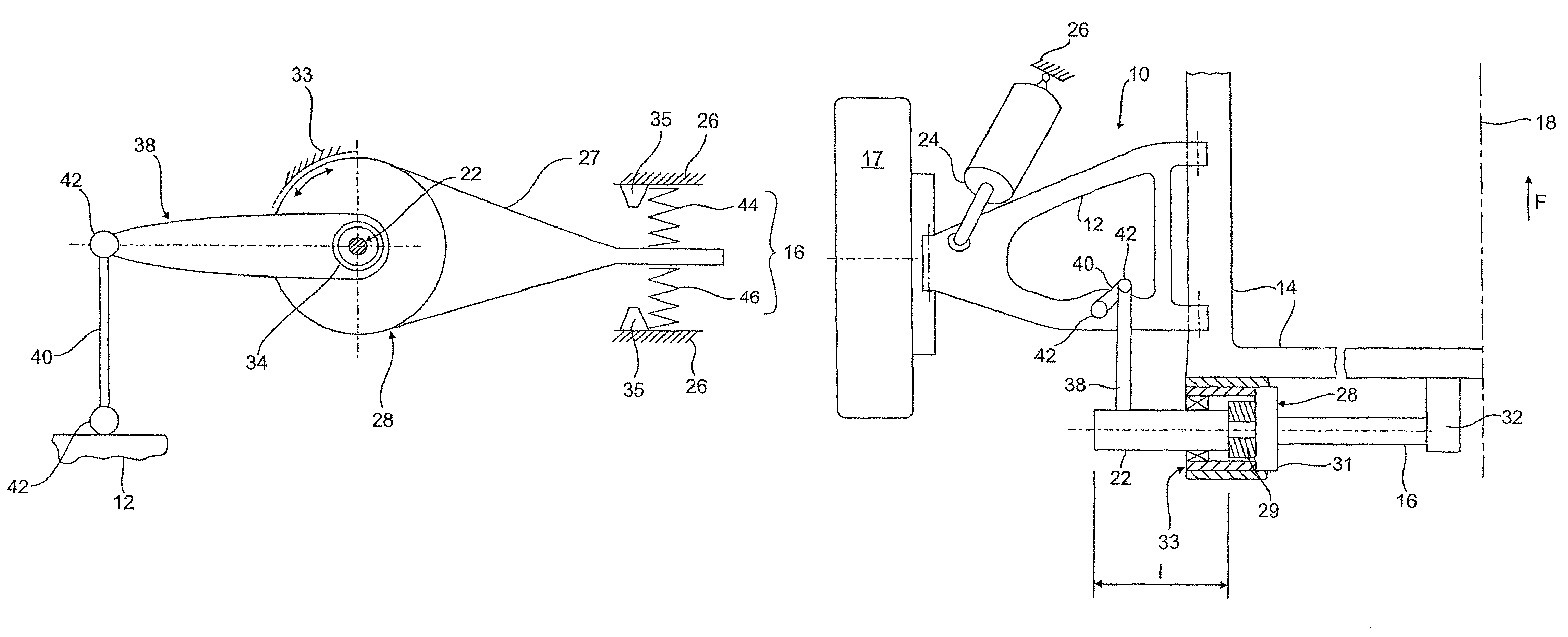
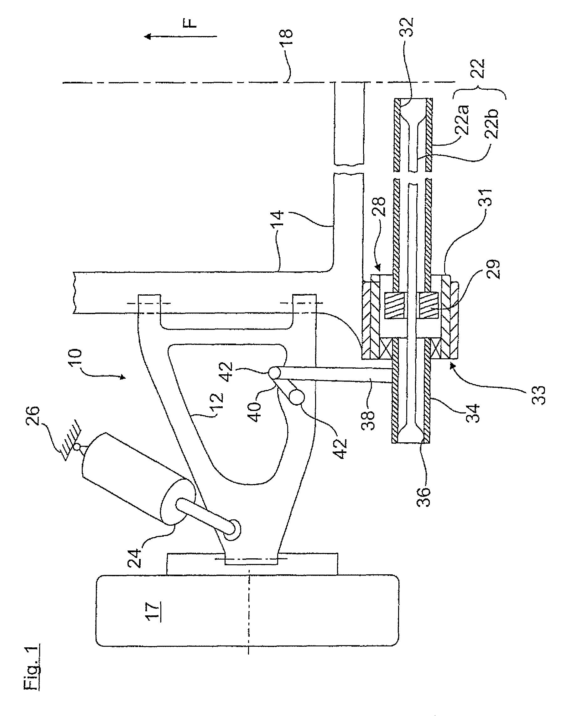
[0026]Turning now to the drawing, and in particular to FIG. 1, there is shown a lower plane of a left-side wheel suspension for motor vehicles designated by 10, with a lower transverse control arm 12 which is articulated, on the one hand, on an only partially shown subframe 14 and, on the other hand, on an only schematically indicated wheel carrier for a rear wheel 17. The u...


PUM


Abstract

A torsion bar spring arrangement for a wheel suspension of a motor vehicle includes an actuator arranged on a vehicle body or on a subframe and constructed to variably pre-tension the torsion bar spring arrangement, a coaxial first torsion bar spring having an output side that is connected by way of an output lever to a wheel suspension element of the wheel suspension, and a housing of the actuator supported on the vehicle body in at least one bearing location for movement in a circumferential direction and resiliently yieldingly supported on the vehicle body in the direction of torsional moments acting on the torsion bar spring by way of at least one spring element.

Description

CROSS-REFERENCES TO RELATED APPLICATIONS[0001]This application claims the priority of German Patent Application, Serial No. 10 2013 002 713.6, filed Feb. 16, 2013, pursuant to 35 U.S.C. 119(a)-(d), the content of which is incorporated herein by reference in its entirety as if fully set forth herein.BACKGROUND OF THE INVENTION[0002]The present invention relates to a torsion bar spring arrangement for a wheel suspension of a motor vehicle.[0003]The following discussion of related art is provided to assist the reader in understanding the advantages of the invention, and is not to be construed as an admission that this related art is prior art to this invention.[0004]In conventional torsion bar spring arrangements, the torsion bar spring is composed of only two components, namely a tubular spring and solid bar spring. The remaining components in the load path are designed to be absolutely rigid without affecting the overall spring constant of the system. For example, when a softer torsi...

Claims


Application Information

Patent Timeline
Patent Type & Authority Patents(United States)
IPC IPC(8): B60G17/02B60G11/15B60G11/48B60G11/18B60G11/50B60G21/055
CPCB60G17/025B60G11/15B60G11/48B60G11/50B60G21/0555B60G11/183B60G2202/12B60G2202/134B60G2202/42B60G2206/604B60G2204/1224
Inventor MOHRLOCK, DOMINIKSCHINDLER, ANDREASBERINGER, HEINRICHSCHMITT, JOACHIM
Owner AUDI AG
Why Eureka
Try Eureka