Systems and methods for automating the application of friction-modifying coatings

Active Publication Date: 2015-08-18
DBI HLDG LLC +1
View PDF47 Cites 10 Cited by
  • Summary
  • Abstract
  • Description
  • Claims
  • Application Information

AI Technical Summary

Benefits of technology

[0016]A further benefit of this invention is an increase in the application rate of the friction-modifying coating. The conventional method of application results in an application rate of approximately 1,000 square yards per day. Using the systems and methods of this invention, the application rate can be increased to over 10,000 square yards per day, although conventional rates of application are possible if desired. This will have the benefit of decreasing the amount of time required to complete a project as well as a reduction in the disruption of the traffic, due to closure of the surface being coated.
[0017]A further benefit of this invention is a reduction in the time that transpires from the time the binder is applied to the substrate and the time the filler is added to the binder. For the previous methods of application, several minutes can pass before the filler is added to the binder. This is the result of the time required to mix and then manually apply the binder and then the filler to the binder. The method of this invention results in the filler being added almost immediately to the binder in sequence and in virtually a one-step process. The lapsed time between application of the binder and addition of the filler should be short, preferably less than 5 seconds. This results in greater filler penetration and a more durable coating.
[0018]Another benefit of this invention is the uniformity of the friction-modifying coating and filler within the composition. Under the conventional methods of application, the filler is added to the binder either by manually shoveling it, or through the use of a manually operated blower. Both of these conventional methods result in variability in the filler density per square foot of substrate surface, and patches containing too much filler and others not containing enough filler. The method of the present invention results in the uniform application of filler across the width and length of the surface being coated. Thus, there is high uniformity of filler density per square foot, an

Problems solved by technology

Thus, the time between the application of the binder and the addition of the filler is very short, such as less than a few

Method used


Image

  • Systems and methods for automating the application of friction-modifying coatings
  • Systems and methods for automating the application of friction-modifying coatings
  • Systems and methods for automating the application of friction-modifying coatings

Examples


Embodiment Construction

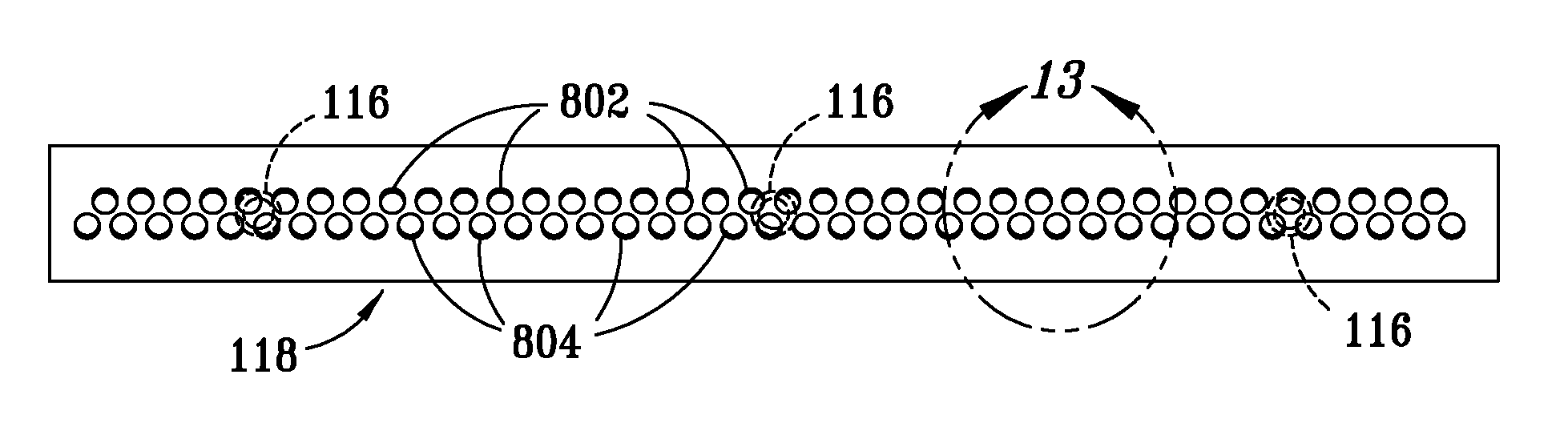
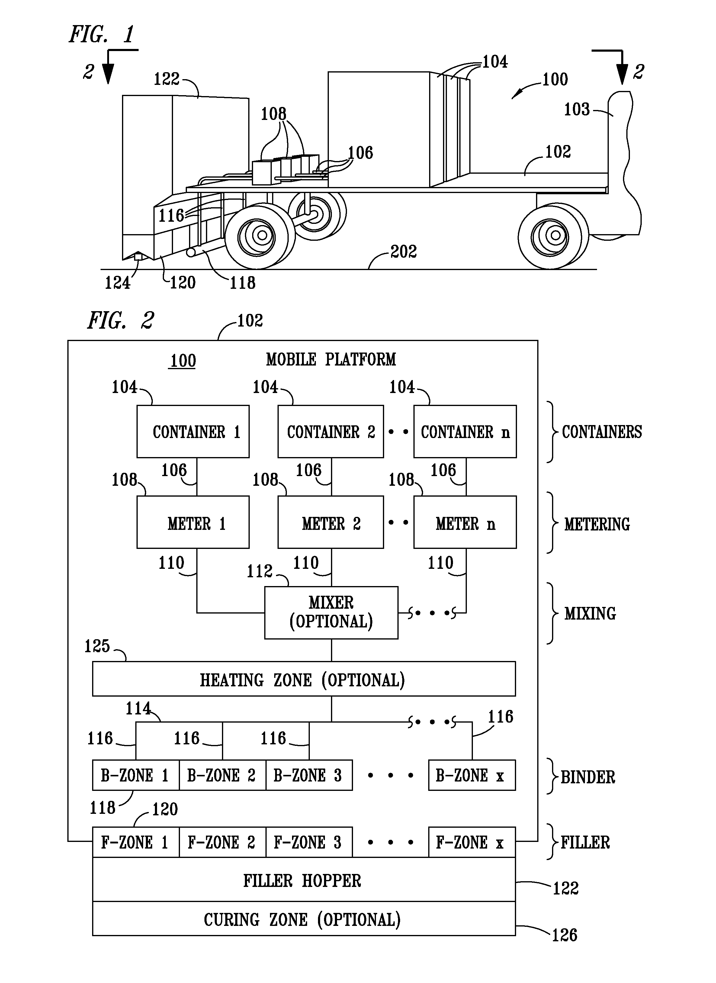
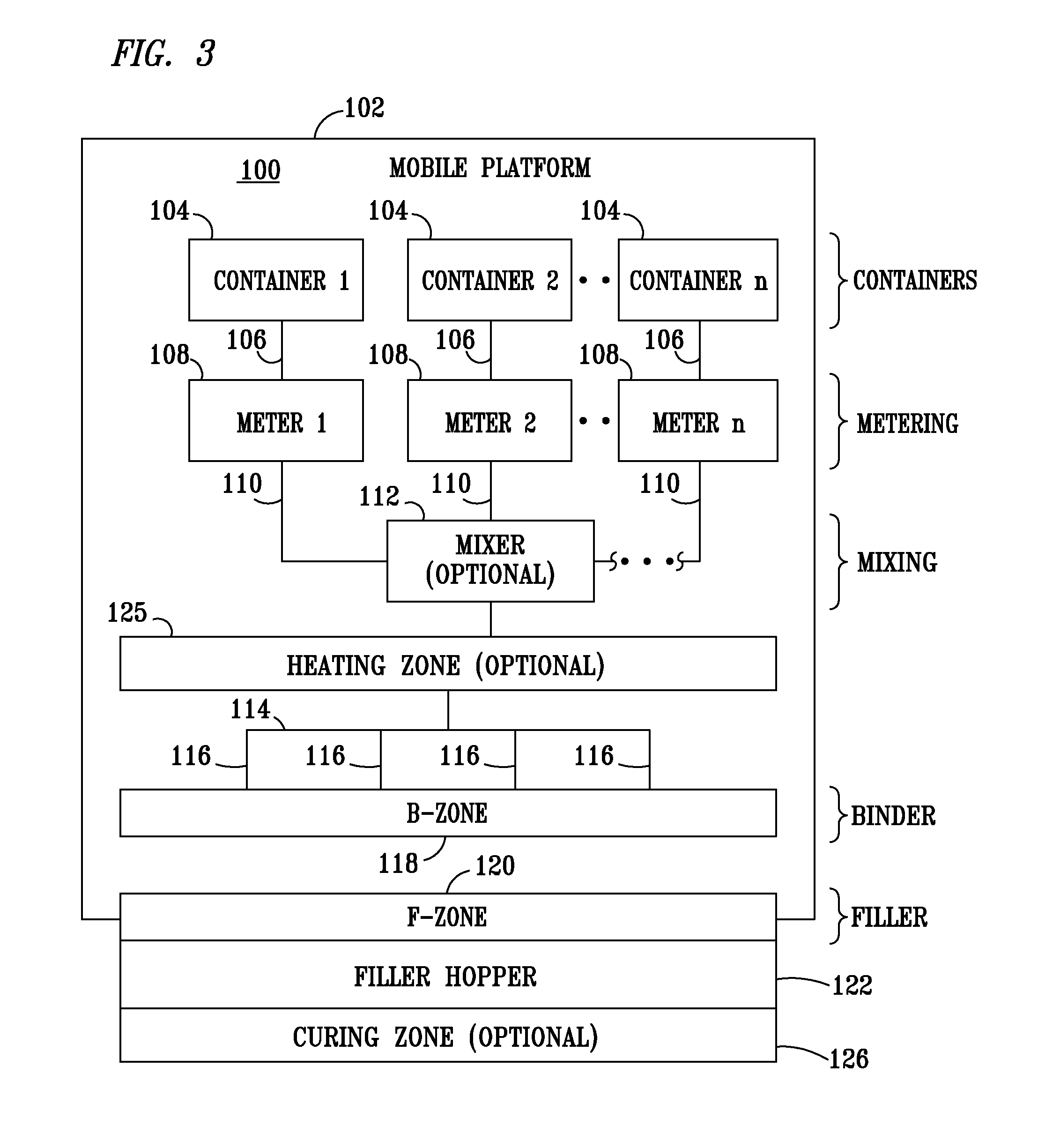
[0036]The invention relates to the controlled preparation and application of friction-modifying coatings, comprising a binder and filler, to surfaces subject to vehicular, human, and / or animal traffic. Friction-modifying coatings are applied to areas where the friction coefficient of the surface needs to be increased in order to reduce skidding or slipping, making it safer and / or better for its intended purpose. Included in the many substrate surfaces which can benefit from the application of these coatings are pathways, walkways, highways and roadways, bridge decks, parking lots, school zones, road crossings, railway crossings, dangerous intersections, bike lanes, toll lanes, sharp corners, intersections, overpasses, hospital zones, playgrounds, gymnasiums, and the like.

[0037]In the discussion of the FIGURES, the same reference numerals will be used throughout to refer to the same or similar components. In the interest of conciseness, various components known to the art, such as me...


PUM


Abstract

A system and method for the application of friction-modifying coatings to roadways, walkways, pathways and other areas subject to vehicular, human or animal traffic, the system and method comprising the controlled, simultaneous application of binder and filler to a surface of a substrate, using a mobile device which passes over the substrate as the binder and filler are being applied. Both the binder and the filler are precisely and accurately metered onto the substrate, ensuring uniform coating thickness and performance. The method of this invention also enables the use of different binding systems and precise control over mixing ratios for multi-component binders.

Description

TECHNICAL FIELD[0001]The present invention relates generally to a system, and associated method, for applying friction-modifying coatings to a surface, and more particularly, for automating the application from a mobile platform of friction-modifying coatings to a surface of a substrate, such as a roadway.BACKGROUND[0002]The construction and public safety industries are constantly looking for means to make substrates, such as roadways, pathways, and other high-use areas, safer for vehicular and human traffic. One developing area is in the application of friction-modifying coatings to surfaces of substrates to help increase their coefficient of friction, thereby reducing slippage and skidding and making them safer for their intended use. In particular, the roadway industry is trying to reduce the number of accidents caused by loss of tire grip on bridges, curves, intersections, and school zones. Speed, tire condition, and weather conditions can all play a role in these accidents; how...

Claims


Application Information

Patent Timeline
IPC IPC(8): E01C19/16E01C19/20
CPCE01C19/16E01C19/17E01C23/06B05B1/20
Inventor STONE, JR., JACK D.
Owner DBI HLDG LLC
Why Eureka
Try Eureka