
Method for fastening a cover plate to a frame structure

Active Publication Date: 2015-08-18
LUCK JOCHEN
View PDF20 Cites 0 Cited by
  • Summary
  • Abstract
  • Description
  • Claims
  • Application Information

AI Technical Summary

Benefits of technology

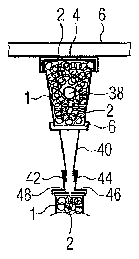
The invention is about a method to fasten two cover layers together, like a vacuum insulating panel or a photovoltaic panel on a frame. The method allows for easy and rapid installation of stable and durable faces, while maintaining the vacuum in the panel for long-term preservation. The frame structure is designed to provide good performance and to meet the requirements of various needs.

Problems solved by technology

One of the most important challenges for the future is to drastically reduce the consumption of raw materials.
In particular in the building sector, considerable potential is untapped here both for future projects and in the existing situation.
A further challenge is to economically obtain renewable energy, as far as possible without competition with food production and nature conservation and to make it storable.
The particular challenge is both the edge connection, which has to combine minimum heat conduction with maximum diffusion-tightness and slightly resilient behaviour.
Likewise, the ratio of volume to surface is problematic to achieve and maintain the high vacuum and requires very clean working and excellent cleaning of the surfaces before joining.

Method used


Image

  • Method for fastening a cover plate to a frame structure
  • Method for fastening a cover plate to a frame structure

Examples


Embodiment Construction

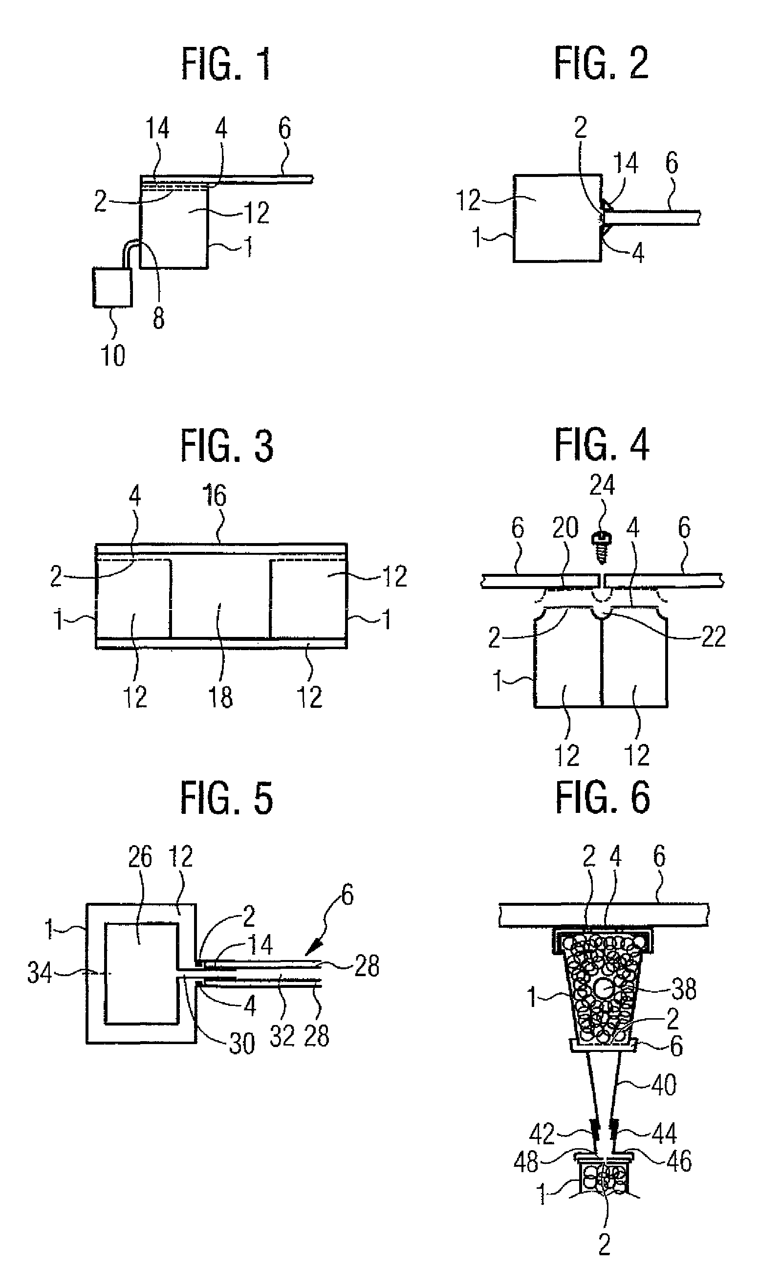
[0052]The same parts are provided in all the figures with the same reference numerals.

[0053]FIG. 1 schematically shows a cross-section of a frame structure 1. The latter has a number of channels 2 towards a surface 4, on which a cover plate 6 is to be fastened. Furthermore, the frame structure 1 has an opening 8, to which a vacuum pump 10 is connected. The vacuum pump 10 is put into operation so that the cavity 12, which is gas-tight except for the described channels 2 and opening 8, has a negative pressure in comparison to the surroundings.

[0054]The cover plate 6 is then brought over the channels 2 and fixed there, free of tension, by the suction of the negative pressure in the cavity 12. For better retention and to reinforce the suction, a sealing element 14 is arranged here, said sealing element having holes adapted to the channels 2, so air can pass, but being sealed towards the exterior.

[0055]For a permanent fixing of the cover plate 6, the vacuum pump 10 is now removed and the...


PUM

PropertyMeasurementUnit
Pressureaaaaaaaaaa
Structureaaaaaaaaaa
Adhesivityaaaaaaaaaa

Abstract

A method for fastening a cover plate (6) to a frame structure (1) formed on the cover plate (6) is to easily and rapidly allow the erection of faces that are stable and durable in the long term and simultaneously, in the case of vacuum insulating panels, allow particularly good preservation of the vacuum in the panels. For this purpose, the frame structure (1) comprises a cavity (12), a number of channels (2) connecting the cavity (12) to the surface (4) and an opening (8) to connect a vacuum pump (10), the vacuum pump (10) being connected to the opening (8) and put into operation, the cover plate (6) being arranged on the surface (4) above the channels (2), and the cover plate (6) being fixed to the surface (4).

Description

CROSS-REFERENCE TO RELATED APPLICATIONS[0001]This application is the U.S. National Stage of International Application No. PCT / EP2012 / 004443, filed Oct. 24, 2012, which designated the United States and has been published as International Publication no. WO2013 / 060450and which claims the priority of German Patent Application, Ser. No. 102011117145.6, filed Oct. 28, 2011, pursuant to 35 U.S.C. 119(a)-(d).BACKGROUND OF THE INVENTION[0002]The invention relates to a method for fastening a cover plate on a frame structure. It furthermore relates to a frame structure suitable for carrying out the method. Moreover, the invention relates to a method for fastening a cover plate comprising two cover layers arranged substantially parallel to one another on a frame structure and a frame structure suitable for carrying out the method.[0003]One of the most important challenges for the future is to drastically reduce the consumption of raw materials. In particular in the building sector, considerabl...

Claims


Application Information

Patent Timeline
IPC IPC(8): E04B1/74E04B2/00E04B1/80
CPCE04C2/44E04B1/803Y02B80/12Y10T29/49826Y02A30/242Y02B80/10
Inventor LUCK, STEFAN
Owner LUCK JOCHEN
Learn More