MEMS utility meters with integrated mass flow sensors

a technology of mass flow sensor and utility meter, which is applied in the direction of liquid/fluent solid measurement, volume metering, instruments, etc., can solve the problems of inability of flow sensor to provide the desired dynamical flow range, undesired erratic measurement of straight pipes without additional flow conditioning, etc., to reduce the dynamical measurement range, improve the effect of flow condition and reduce the effect of dynamical measurement rang

Active Publication Date: 2015-08-18
M TECH INSTR HLDG
View PDF3 Cites 11 Cited by
  • Summary
  • Abstract
  • Description
  • Claims
  • Application Information

AI Technical Summary

Benefits of technology

[0006]Usually a MEMS silicon thermal flow sensor is incapable to provide the desired dynamical flow range with flow stability at the medium gas pressure range since the mass flow in principle will have a reduced dynamical measurement range with proportional to the increment of gas pressure. A straight pipe without additional flow conditioning will have undesired erratic measurement due to flow irregularities. Further, the maximum dynamic measurement range of calorimetric mass flow sensor shall be restrained by the boundary layer limitation. It is therefore the intension of this invention to provide a stable flow condition whilst having a desired dynamic range capability. Therewith, the current invention shall have properties in many aspects of differentiation include dynamic metrology capability, faster response, lengthy lifetime, easiness of integration and lower cost.
[0007]This meter shall have one pair of flanges as for pressurized pipe connection. The meter body which is also serves as the flow channel where the sensor probe assembly is inserted for metering. The flow channel is designed using a standard Venturi structure where the sensor probe assembly is positioned at the center of the smallest inner diameter along the Venturi structure to improve flow stability. Furthermore, two different flow conditioners are placed in series at the inlet end of the flow channel. The flow conditioner right at the inlet is a flow straightener; and the other one which is located at a distance 2˜5 times of the pipe diameter from the inlet end is a flow profiler. The optimum distance for the flow profiler from the inlet end of flow channel is preferably at a length of 3 times of the pipe diameter. The sensor probe assembly shall have an electronic control board with as memory chip that can be used to store the calibration data as well as other metrology data with enhanced data security. This sensor assembly unit therefore can be independently performing the metrology task. The identical flow conditioning and configuration can provide that the meter body has the same construction such that the assembly can be recovered to its origin performance when it is replaced by other duplicated ones. The sensor assembly with its key component of an integrated MEMS chip has extended the measurement dynamic range using both the calorimetric and anemometric measurement principle. Such that the invented meter shall have an extended dynamic turn-down (measurement) ratio over 1000:1 depending on the calibration procedure. But in most cases it shall have a dynamic range of 100:1 for practical applications at a less calibration cost.
[0008]Another embodiment in the current invention is that the sensor assembly consists of a forced flow channel that has a diameter of one fourth to one eighth range of the pipe channel. One sixth of the pipe inner diameter for the forced flow channel is considered to be optimum. The sensor assembly inserted into the flow channel should be positioned such that the sensing element on the MEMS silicon mass flow sensor is at the center of the flow channel. This embodiment in the current invention shall then have the advantages to further constrain the flow into a uniform turbulence flow after passing through the flow profiler such that the sensing element, shall always measure the flow velocity in a same flow formality within the desired dynamic range. The current invention further shall have another advantage with more flexibility and tolerance for the sensor alignment to the central point of flow channel since the flow channel size of the meter assembly is much larger than the dimension of a microfabricated MEMS sensing element.
[0009]As for the city gas custody transfer and tariff applications, the current invention provides a solution for large dynamic range without the needs of temperature and pressure compensation since the MEMS thermal flow sensor is measuring the flow medium in a mass base instead of volume base. The sensor assembly package not just only provides enhanced flow stability but also an independent service unit which is easy for onsite service and maintenance.

Problems solved by technology

Usually a MEMS silicon thermal flow sensor is incapable to provide the desired dynamical flow range with flow stability at the medium gas pressure range since the mass flow in principle will have a reduced dynamical measurement range with proportional to the increment of gas pressure.
A straight pipe without additional flow conditioning will have undesired erratic measurement due to flow irregularities.

Method used


Image

  • MEMS utility meters with integrated mass flow sensors
  • MEMS utility meters with integrated mass flow sensors
  • MEMS utility meters with integrated mass flow sensors

Examples


Embodiment Construction

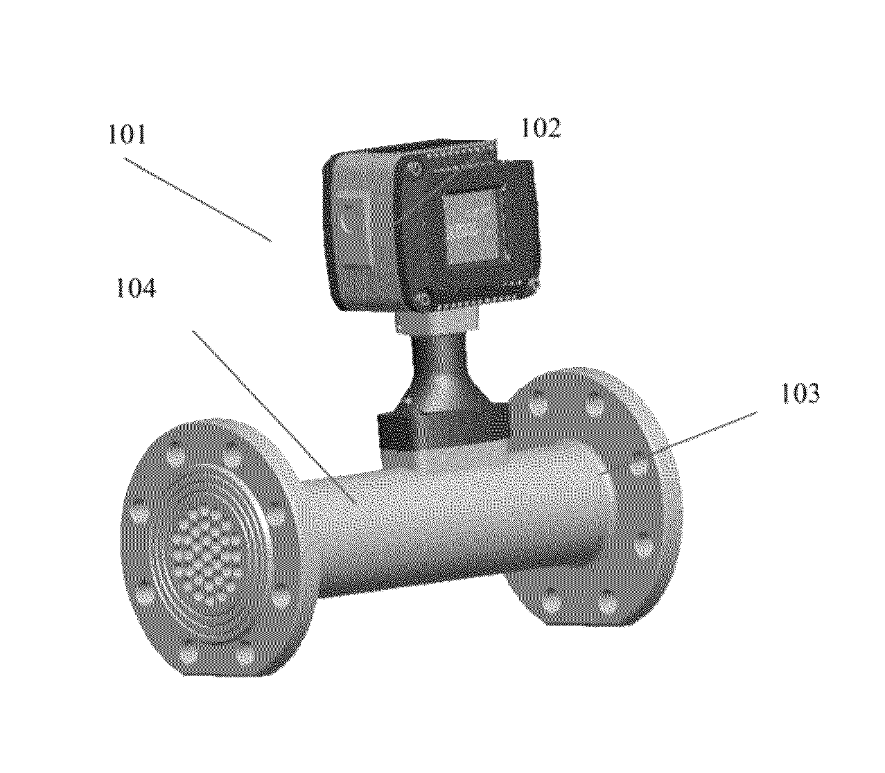
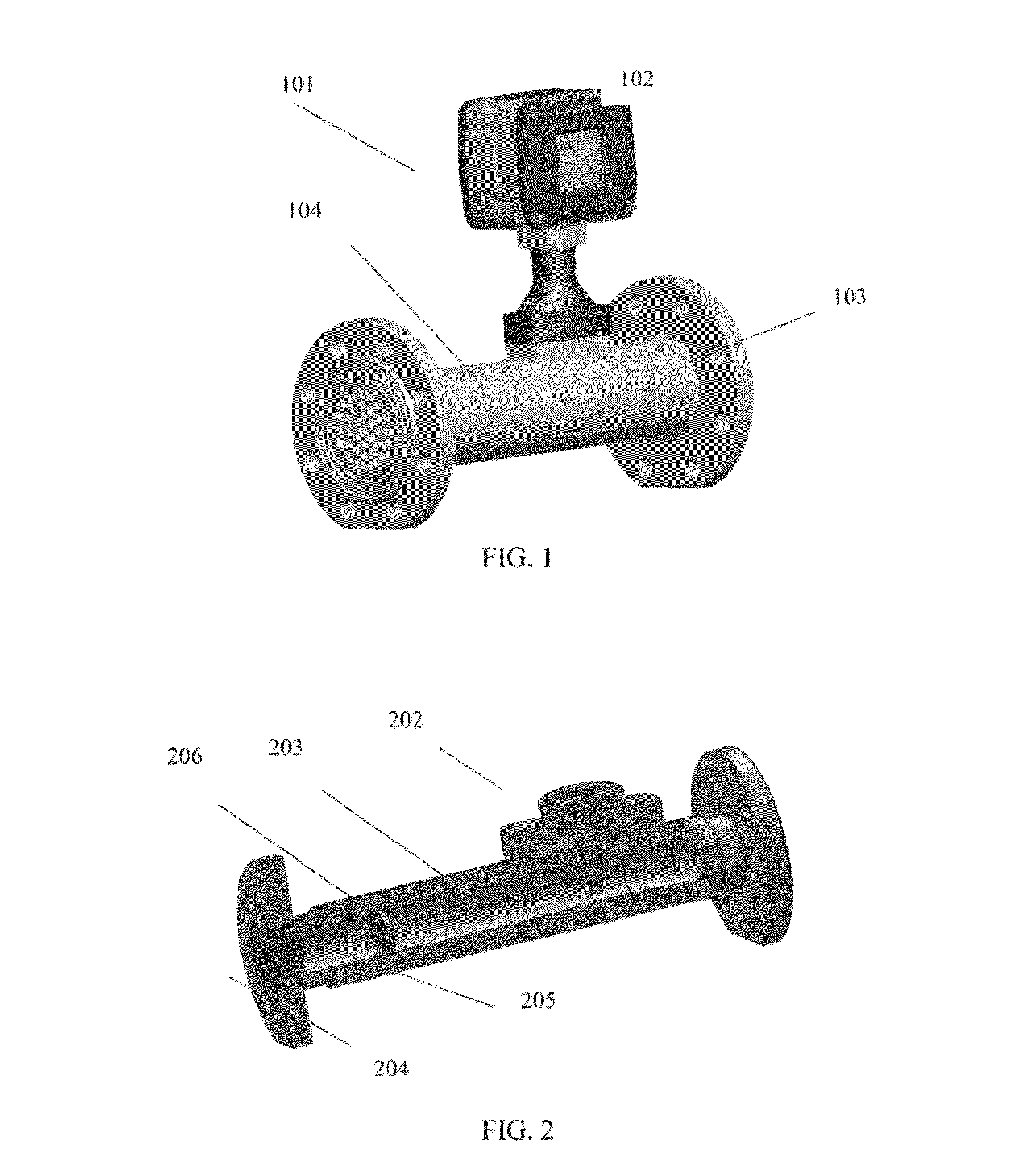
[0015]FIG. 1 illustrates a complete assembly view of the utility gas meter. The utility gas meter mainly composes of four major components: the meter head (101), the display (102), the connection flange (103), and the meter body (104).

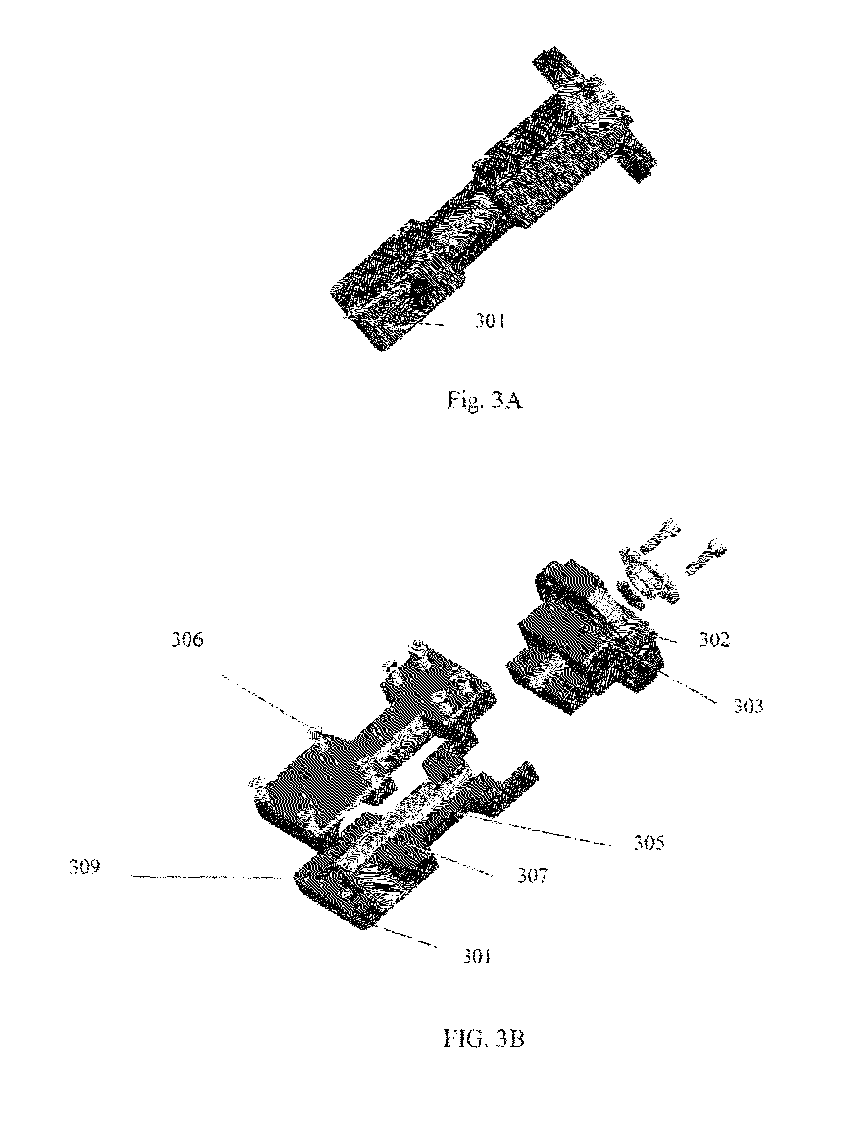
[0016]FIG. 2 depicts a profile view for a pictorial illustration of the complete assembled utility gas meter without the meter head (101) and display (1102). Portion of the flow channel is built with a Venturi structure (203). In order to ensure the flow stability, two flow conditioners are installed in the flow channel. The one called flow straightener (204) is installed right in the inlet end of the flow channel (206); and the second one called flow profiler (205) is installed at a distance about 2˜5 times of the pipe diameter from the inlet end. In the optimum situation, the location of the flow profiler is preferred to be at a distance of 3 times of the pipe diameter from the inlet end. The sensor probe assembly (202) is inserted into the Venturi s...


PUM


Abstract

This invention is related to an apparatus which incorporates a microfabricated silicon mass flow sensor to measure city gas flow rate in a medium pressure range for utility industry which is dominated by conventional mechanical meters such as turbine and rotary meters. The microfabricated mass flow sensor is so called micro-electro-mechanical systems (a.k.a. MEMS) device. Due to the small feature size of micro scale for MEMS mass flow sensor, the invented apparatus includes many advantages such as low power consumption, compact package, high reliability and extended dynamic measurement range. This apparatus is also provided with a stable flow conditioning to achieve a desired dynamic range capability. Furthermore, because of the high accuracy characteristic, the apparatus in this invention could be applied for custody transfer or tariff in utility industry as well.

Description

[0001]We claim the priority to U.S. provisional application Ser. No. 61 / 554,930, filed on Nov. 2, 2011.BACKGROUND OF THE INVENTION[0002]City gas meters in the medium pressure range for custody transfer have been dominated by mechanical technology such as turbine or rotary meters. These meters have been on market for over 160 years enjoying excellent service, life and reliability. However, the turbine meter is greatly suffered from a small dynamic range while the rotary meter is quite vulnerable to the damage caused by floating particles in the flow medium. For the rotary meter, event it is only partially clogged or damaged by the floating particles; the meter would still be affected in terms of repeatability and accuracy of flow measurement. Once the rotary meters got completely clogged, the rotary meter will stop rotating and fail the functionality. In addition, these mechanical meters requires heavy maintenances services and an add-on flow computer to compensate the environment va...

Claims


Application Information

Patent Timeline
Patent Type & Authority Patents(United States)
IPC IPC(8): G01F1/68G01F15/00G01F25/00G01F1/684
CPCG01F1/6845G01F1/6842G01F15/00G01F25/0007G01F25/10
Inventor YANG, XIANGYOUFENG, YONGJIANG, SUGANGCHEN, CHIH-CHANGHUANG, LIJI
Owner M TECH INSTR HLDG
Why Eureka
Try Eureka