Measuring apparatus

a technology of measuring apparatus and elevation direction, which is applied in the direction of instruments, ultrasonic/sonic/infrasonic image/data processing, and reradiation, etc., can solve the problems of deteriorating reconstruction increasing the physical load on the human object, and significantly reducing image resolution in elevation direction, so as to improve image resolution and simple structure without deteriorating the speed of obtaining image data

Active Publication Date: 2015-08-25
CANON KK
View PDF32 Cites 1 Cited by
  • Summary
  • Abstract
  • Description
  • Claims
  • Application Information

AI Technical Summary

Benefits of technology

[0006]An object of the present invention is to improve image resolution in the elevation direction with a simple structure without deteriorating a speed of obtaining image data in a measuring apparatus for obtaining image data while moving a probe in the elevation direction continuously.
[0008]According to the present invention, image resolution in the elevation direction may be improved with a simple structure without deteriorating a speed of obtaining image data in the measuring apparatus for obtaining image data while moving the probe in the elevation direction continuously.

Problems solved by technology

However, this method has a problem that image resolution in the elevation direction significantly reduces as compared with image resolution in a slice plane.
A first reason is that if the mechanical scan speed by the probe is decreased so as to reduce a pitch of obtaining the cross-sectional slice images, it may increase a physical load to the human object.
In addition, a second reason is that effective angular aperture of the one-dimensionally arranged probe in the elevation direction is smaller than that in the arrangement direction, so that a reconstruction resolution in the elevation direction is deteriorated.
However, the number of transmission and reception elements increases, which leads to another problem that a necessary electric circuit scale increases, making it difficult to achieve the practical use of the apparatus in terms of cost.

Method used


Image

  • Measuring apparatus
  • Measuring apparatus
  • Measuring apparatus

Examples


example 1

[0029](Transmission of Ultrasonic Wave)

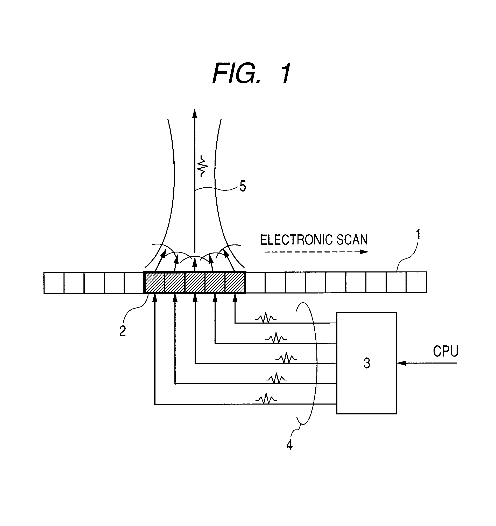
[0030]With reference to FIGS. 1 and 2, Example 1 of the present invention is described. FIG. 1 is a diagram illustrating a principle of a linear scanning method of transmitting an ultrasonic beam 5 using a one-dimensionally arranged probe 1 (hereinafter, simply referred to as “probe”). The ultrasonic wave beam may also be emitted from one transmission and reception element of the probe 1. However, usually, as illustrated in FIG. 1, a plurality of transmission and reception elements are driven (hereinafter, a group of elements to be driven is referred to as “transmission and reception element group 2”), so as to emit a high intensity and high directivity ultrasonic beam 5. In this case, a transmission control circuit 3 applies a pulse-like drive signal 4 to individual transmission and reception elements of the transmission and reception element group 2 at individual timings, so that each transmission and reception element is applied with the dri...

example 2

[0051]FIG. 7 illustrates a structure relating to a reception process performed by a measuring apparatus of Example 2. In Example 2, the delay and sum is performed by the apodizing process in which a weight is added to each signal. The apodizing process is effective for performing optimal adjustment of an aperture size according to a focal point position of the delay and sum, or for reducing influence of an interference acoustic wave entering from other directions. In Example 2, weight multiplying circuits 41 and 42 are additionally provided in the preceding stages of the add circuit 8 of the first delay and sum circuit 9 and the add circuit 26 of the second delay and sum circuit 27, respectively, so that the apodizing process may be performed. The weight in this case may be fixed or may be variable according to signal reception time. Note that in Example 2, the apodizing process is performed in both the first delay and sum circuit 9 and the second delay and sum circuit 27, but the a...

example 3

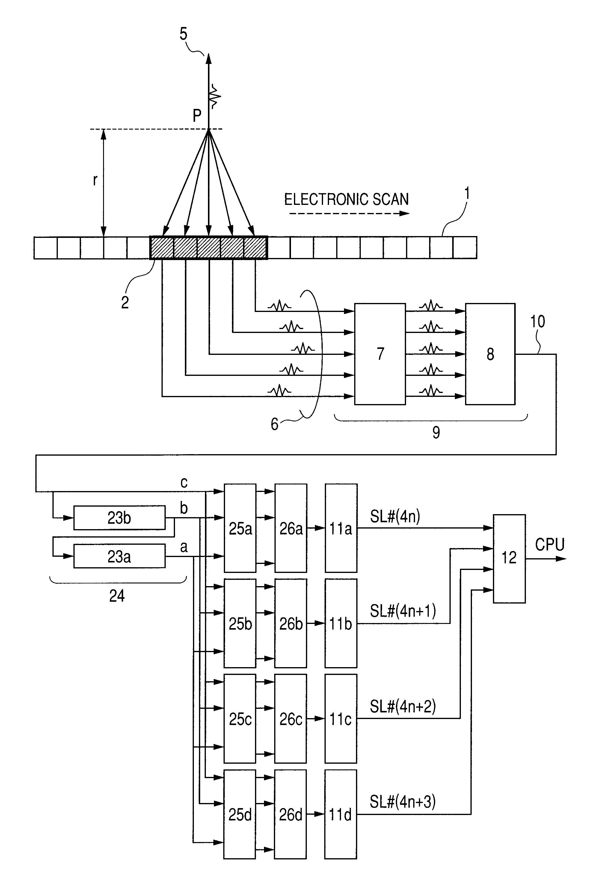
[0052]FIG. 8 illustrates a structure relating to a reception process performed by a measuring apparatus of Example 3. In Example 3, a plurality of second delay and sum circuits are provided, and the plurality of second delay and sum circuits have different focal point positions serving as a reference of the delay and sum (position in the elevation direction).

[0053]In FIG. 6, it is supposed that the focal point P exists in the cross-sectional slice plane obtained by the mechanical scan for a simple description. However, the point P may be at any position in principle. Therefore, in Example 3, the plurality of second delay and sum circuits set the focal point in different cross-sectional slice planes so as to perform the delay and sum process. Specifically, the measuring apparatus of Example 3 includes four second delay and sum circuits constituted of delay adjustment circuits 25a, 25b, 25c, and 25d, and add circuits 26a, 26b, 26c, and 26d. The second delay and sum circuits are each s...


PUM


Abstract

Provided is a measuring apparatus, including: a moving mechanism for moving a probe in an elevation direction; a first delay and sum circuit for performing delay and sum of reception signals at individual positions along the elevation direction to output a first add signal; a signal extraction circuit for letting an output of the first delay and sum circuit to pass through delay circuits to output in parallel first add signals obtained at different positions; a second delay and sum circuit for performing delay and sum of the first add signals output from the signal extraction circuit to output a second add signal; and an image processing circuit for generating image data by using the second add signal. Accordingly, image resolution in the elevation direction may be improved with a simple structure without deteriorating an image obtaining speed in the measuring apparatus for obtaining an ultrasonic image.

Description

TECHNICAL FIELD[0001]The present invention relates to a measuring apparatus which obtains information inside an object using an acoustic wave, and more particularly, to a measuring apparatus having a probe that is mechanically scanned.BACKGROUND ART[0002]Conventionally, as an effective image diagnosis apparatus for early detection of breast cancer, there is known an x-ray mammography apparatus. Further, in recent years, there is developed a photoacoustic imaging method in which a pulse laser beam is irradiated onto a living body instead of an X-ray, so as to image a three-dimensional structure inside the living body based on a photoacoustic wave induced by thermal expansion of an optical absorber inside the living body. This apparatus has received attention as a new mammography apparatus that may easily diagnose a potential tumor such as an abnormal growth of new blood vessels.[0003]Such a mammography apparatus has a feature that an abnormal region which is difficult to detect by ot...

Claims


Application Information

Patent Timeline
Patent Type & Authority Patents(United States)
IPC IPC(8): G01S7/52G01S15/00G01S15/89G10K11/34G10K11/35A61B8/08
CPCG01S7/52046G01S7/52085G01S15/8909G01S15/8915G01S15/8934G01S15/8945G01S15/8997G10K11/346G10K11/352A61B8/483G01S15/8993
Inventor YODA, HARUOOIKAWA, KATSUYANAGAE, KENICHI
Owner CANON KK
Why Eureka
Try Eureka