Radiographic image display device and method for displaying radiographic image

a radiographic image and display device technology, applied in the direction of static indicating devices, instruments, applications, etc., can solve the problems of troublesome stereo image depth perception, inability to accurately reach the position of abnormal shadows, and fatigue of the operator's eyes, so as to improve the accuracy of stereo image perception and reduce eye fatigue of the operator. , the effect of easy movemen

Active Publication Date: 2015-08-25
FUJIFILM CORP
View PDF20 Cites 6 Cited by
  • Summary
  • Abstract
  • Description
  • Claims
  • Application Information

AI Technical Summary

Benefits of technology

[0016]The present invention has been made in view of the above situation, and it is an object of the present invention to reduce the troublesome work for indicating an abnormal shadow with a three-dimensional cursor when displaying a stereo image of radiographic images.

Problems solved by technology

However, matching the sense of depth of the three-dimensional cursor with the sense of depth of the abnormal shadow in a stereo image is very troublesome work.
Therefore, continuously watching such a stereo image with a large stereoscopic effect in order to match the stereoscopic effect of the three-dimensional cursor with the stereoscopic effect of the abnormal shadow makes the eyes of the operator very tired.
In particular, in a stereo biopsy, the tip of the biopsy needle cannot be made to reach the position of the abnormal shadow accurately.

Method used


Image

  • Radiographic image display device and method for displaying radiographic image
  • Radiographic image display device and method for displaying radiographic image
  • Radiographic image display device and method for displaying radiographic image

Examples


first embodiment

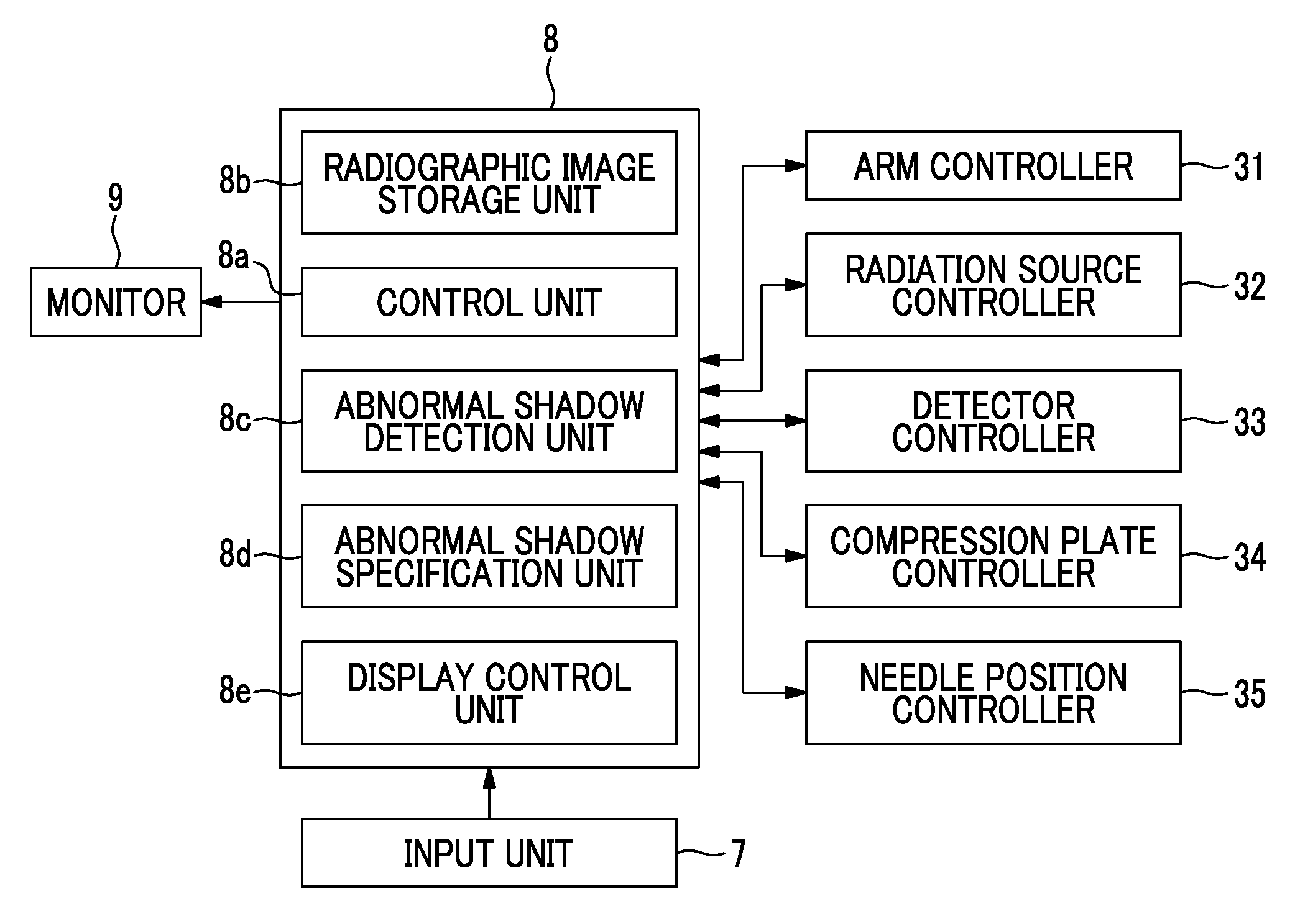
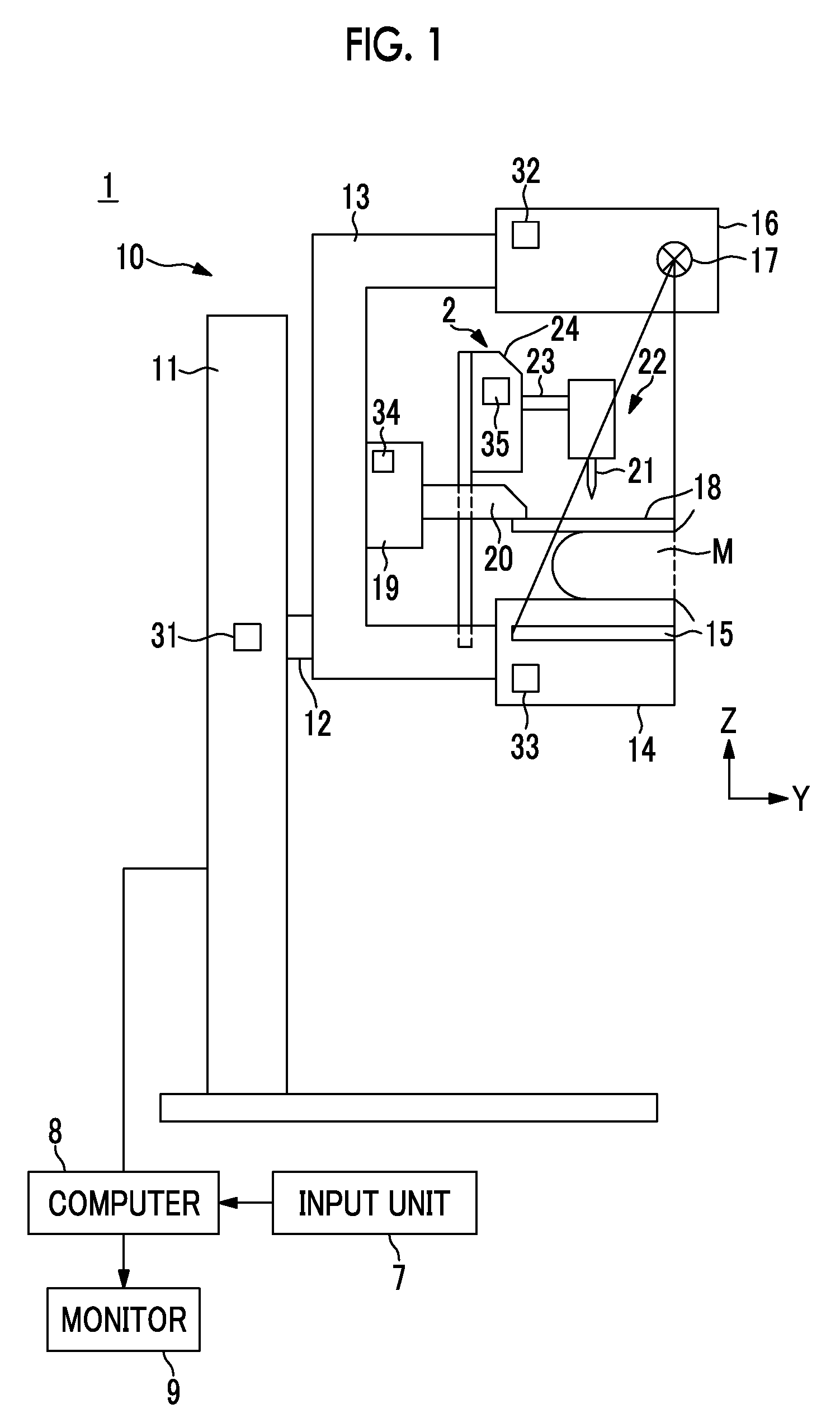
[0058]As shown in FIG. 1, a breast image radiographing and display system 1 of the first embodiment includes a breast image radiographing apparatus 10, a computer 8 connected to the breast image radiographing apparatus 10, a monitor 9 and an input unit 7 connected to the computer 8.

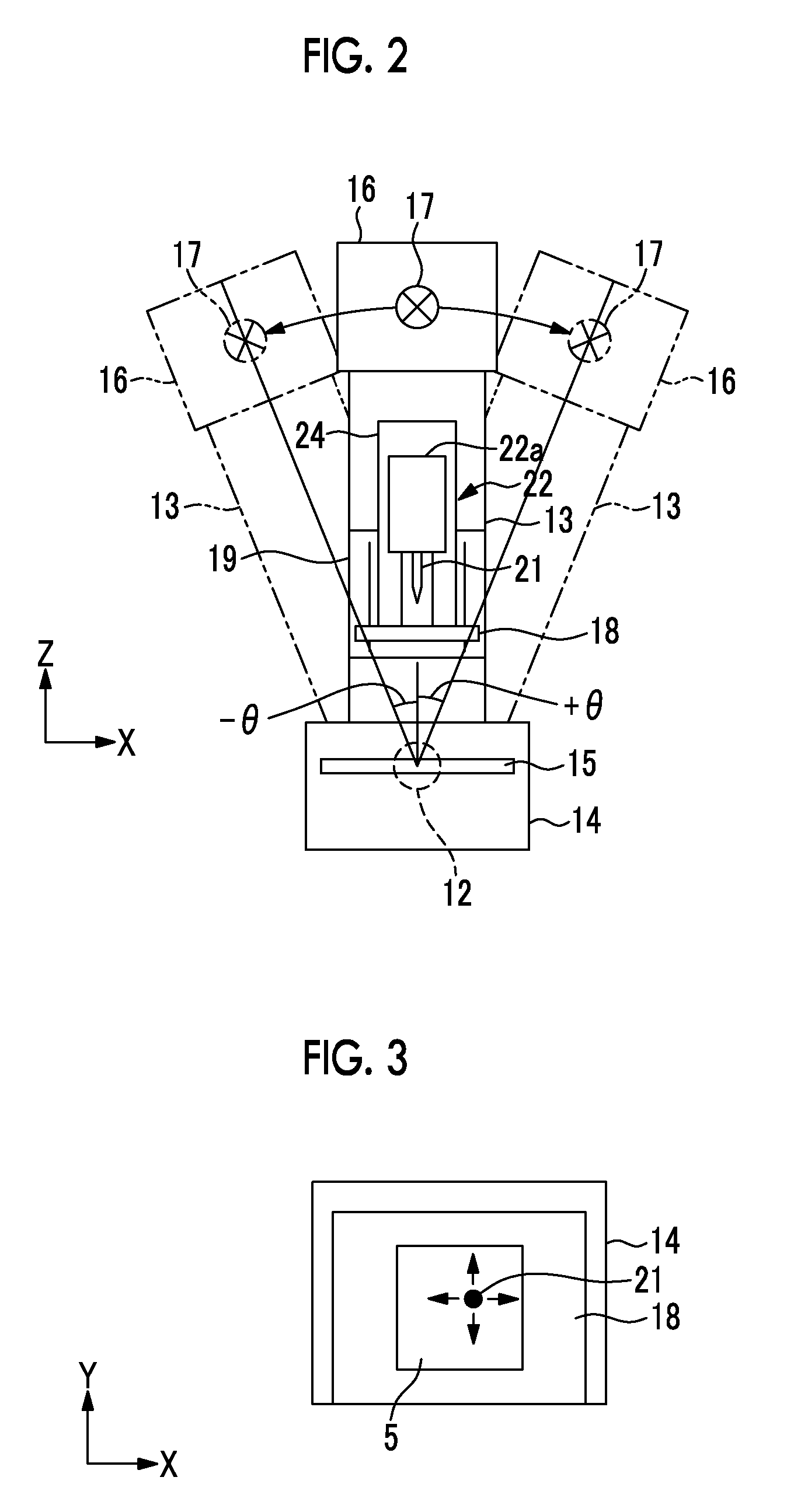
[0059]In addition, as shown in FIG. 1, the breast image radiographing apparatus 10 includes a pedestal 11, a rotary shaft 12 that can rotate and move up and down (in a Z direction) with respect to the pedestal 11, and an arm unit 13 connected to the pedestal 11 by the rotary shaft 12. In addition, FIG. 2 shows the arm unit 13 when viewed from the right side of FIG. 1.

[0060]The arm unit 13 has a shape of a letter C. A radiation plane 14 is fixed to one end of the arm unit 13, and an irradiation unit 16 is fixed to the other end so as to face the radiation plane 14. Rotation and up-and-down movement of the arm unit 13 are controlled by an arm controller 31 provided in the pedestal 11.

[0061]A radiation detec...

second embodiment

[0108]FIG. 16 is a flow chart showing a process performed in the In addition, FIG. 16 shows only the process after the determination in step ST6 of the flow chart shown in FIG. 5 is NO. When the determination in step ST6 is NO, the control unit 8a gives warning for performing third radiographing from a radiographing direction of a third angle that is different from the angle of convergence θ at which the radiographic image GL for a left eye and the radiographic image GR for a right eye are acquired (step ST21). In addition, as warning, an instruction to perform the third radiographing may be displayed on the monitor 9. In addition, a voice may be used, or both the display on the monitor 9 and the voice may be used.

[0109]Thus, an instruction to start the third radiographing is input through the input unit 7 by the operator. Then, if there is an instruction to start radiographing through the input unit 7, third radiographing of the breast M is performed (step ST22). In the third radi...

third embodiment

[0114]FIG. 17 is a flow chart showing a process performed in the In addition, FIG. 17 shows only the process after step ST4 of the flow chart shown in FIG. 5.

[0115]When an abnormal shadow is detected by the abnormal shadow detection unit 8c, the control unit 8a displays one (for example, the radiographic image for a left eye GL) of the two radiographic images GL and GR on the monitor 9 (step ST31). In addition, this radiographic image is displayed in a two-dimensional manner without a stereoscopic effect. Then, as shown in FIG. 18, the operator designates a desired abnormal shadow from the plurality of abnormal shadows using the input unit 7 (step ST32). In addition, the operator designates a desired abnormal shadow by operating the input unit 7 to move the cursor C2 to the desired position of the abnormal shadow.

[0116]Then, the abnormal shadow specification unit 8d specifies an abnormal shadow, which corresponds to the abnormal shadow designated by the operator, in the other radio...


PUM


Abstract

When displaying a stereo image of radiographic images, troublesome work for indicating an abnormal shadow with a three-dimensional cursor is reduced. An abnormal shadow detection unit 8c detects abnormal shadows from radiographic images for left and right eyes for displaying a stereo image. When a plurality of abnormal shadows are detected, an abnormal shadow specification unit 8d specifies abnormal shadows corresponding to each other in two radiographic images. A display control unit 8e gives a three-dimensional cursor to a predetermined abnormal shadow of the plurality of abnormal shadows, and displays a stereo image using the radiographic images for left and right eyes.

Description

CROSS REFERENCE TO RELATED APPLICATIONS[0001]This application is a Continuation of PCT International Application No. PCT / JP2012 / 050152 filed on Jan. 6, 2012, which claims priority under 35 U.S.C. §119(a) to Patent Application No. 2011-004453 filed in Japan on Jan. 13, 2011, all of which are hereby expressly incorporated by reference into the present application.BACKGROUND OF THE INVENTION[0002]1. Field of the Invention[0003]The present invention relates to a radiographic image display device and method for displaying a stereo image of a subject.[0004]2. Description of the Related Art[0005]In an examination at a hospital, a piece of tissue around the lesion may be collected. In recent years, as a method for collecting a piece of tissue without putting a large burden on the patient, a biopsy to puncture the patient with a hollow needle for tissue collection (hereinafter, referred to as a biopsy needle) and collect the tissue embedded in the cavity of the needle has been drawing attent...

Claims


Application Information

Patent Timeline
Patent Type & Authority Patents(United States)
IPC IPC(8): G06F3/033G06T15/60A61B6/02A61B6/12A61B6/00G09G5/08
CPCG06T15/60A61B6/022A61B6/12A61B6/463A61B6/502A61B6/466
Inventor TAJIMA, TAKASHI
Owner FUJIFILM CORP
Why Eureka
Try Eureka