
Elastic wave device and duplexing device

a technology of elastic wave and duplexing device, applied in the direction of impedence networks, electrical devices, etc., can solve the problems of unbalanced-balanced conversion function, and achieve the effect of reducing differences, significant improvement of transmission characteristics and isolation characteristics

Active Publication Date: 2015-08-25
MURATA MFG CO LTD
View PDF28 Cites 0 Cited by
  • Summary
  • Abstract
  • Description
  • Claims
  • Application Information

AI Technical Summary

Benefits of technology

[0012]Preferred embodiments of the present invention provide an elastic wave device having an unbalanced-balanced conversion function capable of reducing a difference between amplitude characteristics between an unbalanced signal terminal and a first balanced signal terminal and amplitude characteristics between the unbalanced signal terminal and a second balanced signal terminal.
[0013]Also, various preferred embodiments of the present invention provide a duplexing device capable of improving transmission characteristics and isolation between a transmission side and a reception side when operating in a differential mode.
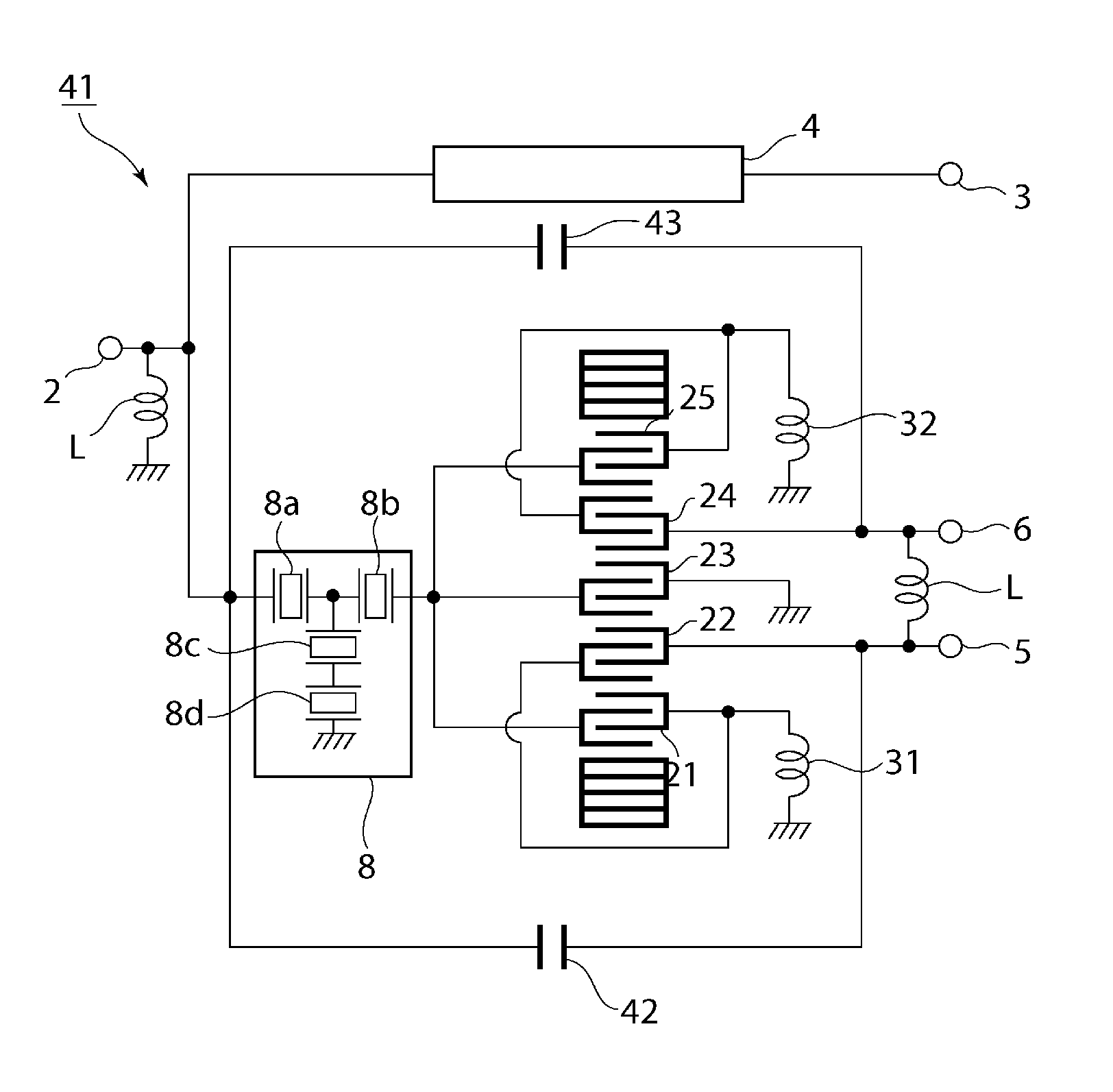
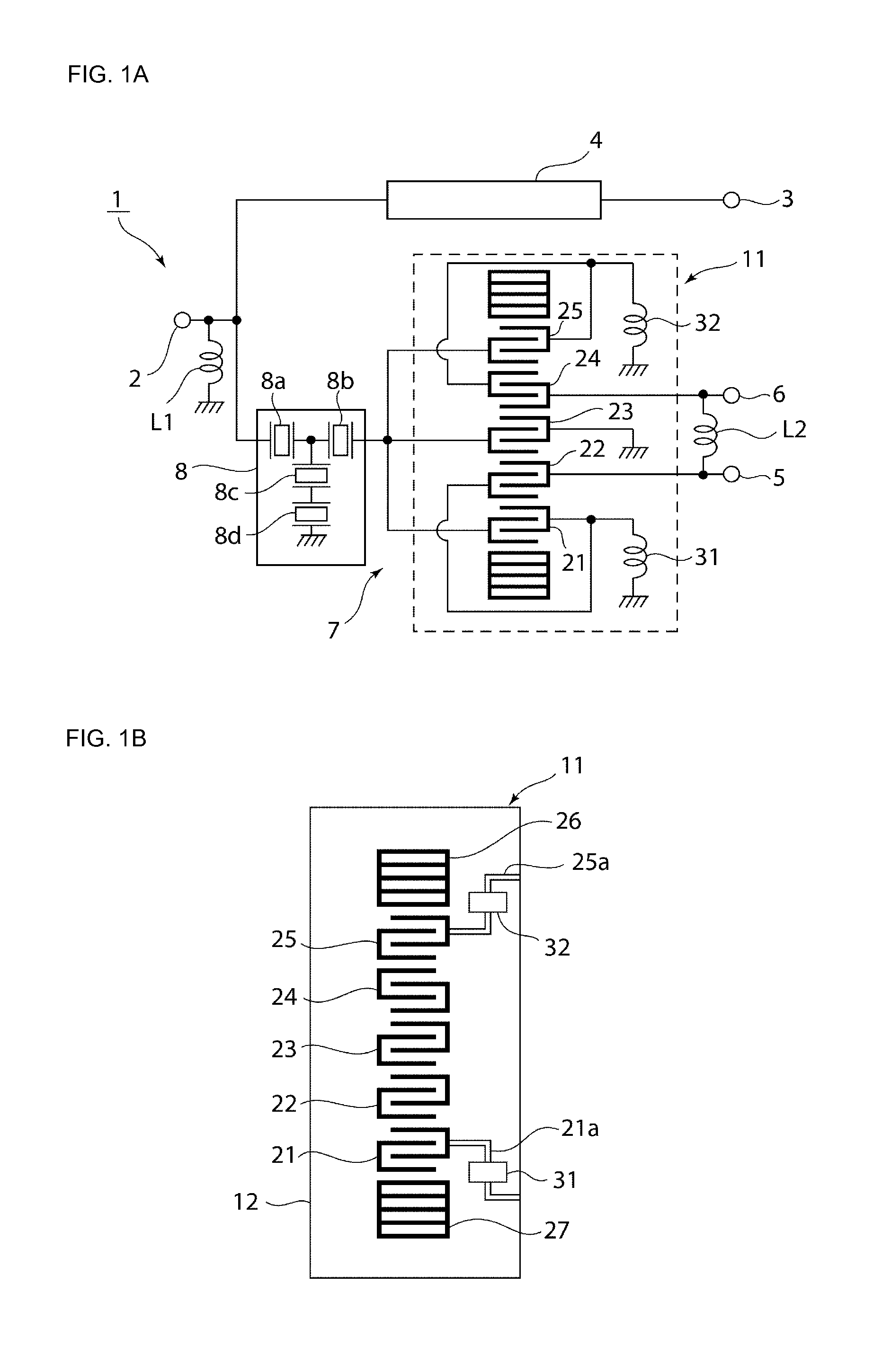
[0017]According to a specific aspect of the elastic wave device according to a preferred embodiment of the present invention, the first inductance is provided between the ground potential and the other end of the first interdigital transducer disposed so as to have the same phase as a signal inputted to the unbalanced signal terminal, the second inductance is provided between the ground potential and the other end of the fifth interdigital transducer disposed so as to have the opposite phase from the unbalanced terminal, and the inductance value L1 of the first inductance is lower than the inductance value L2 of the second inductance. In this case, the positions of attenuation poles in amplitude characteristics of signals obtained from the first and second balanced signal terminals are made different. Accordingly, the difference in amplitude characteristics between the first and second balanced signal terminals is reduced even further.
[0021]In the elastic wave device according to a preferred embodiment of the present invention, the first and second inductances are connected between the first and fifth interdigital transducers and the ground potential, and the inductance values are different between the first inductance and the second inductance, which makes it possible to adjust the amplitude characteristics between the first and second balanced signal terminals. Accordingly, setting the first and second inductance values L1 and L2 so that the respective amplitude characteristics are close to each other makes it possible to reduce the different between the amplitude characteristics as compared to a configuration in which the first and second inductances are not connected.
[0022]The duplexing device according to a preferred embodiment of the present invention includes the elastic wave device according to a preferred embodiment of the present invention as a reception filter circuit, and thus transmission characteristics and isolation characteristics are significantly improved in a differential mode.

Problems solved by technology

An unbalanced-balanced conversion function is realized as a result.

Method used


Image

  • Elastic wave device and duplexing device
  • Elastic wave device and duplexing device
  • Elastic wave device and duplexing device

Examples


Embodiment Construction

[0037]The present invention will be made clear hereinafter through descriptions of specific preferred embodiments of the present invention with reference to the drawings.

[0038]FIG. 1A is a general circuit diagram illustrating a duplexing device according to a first preferred embodiment of the present invention.

[0039]A duplexing device 1 preferably includes an unbalanced signal terminal 2 that is configured to connect to an antenna. An antenna terminal matching inductance L1 is connected between the unbalanced signal terminal 2 and a ground potential.

[0040]A transmission filter circuit 4 is connected between the unbalanced signal terminal 2 and a transmission terminal 3. A reception filter circuit 7 is connected between the unbalanced signal terminal 2 and first and second balanced signal terminals 5 and 6. Note that a phase adjustment circuit 8 is connected between the unbalanced signal terminal 2 and the reception filter circuit 7.

[0041]The first and second balanced signal terminal...


PUM


Abstract

A balanced-unbalanced conversion-type elastic wave device includes an unbalanced signal terminal, first and second balanced signal terminals, and first to fifth interdigital transducers disposed along an elastic wave propagation direction. One end of each of the first, third, and fifth interdigital transducers is connected in common to the unbalanced signal terminal, one end of each of the second interdigital transducer and the fourth interdigital transducer is connected to the first and second balanced signal terminals respectively, a first inductance is connected between the first interdigital transducer and a ground potential, and a second inductance is connected between the fifth interdigital transducer and the ground potential. First and second inductance values of the first and second inductances, respectively, are different.

Description

BACKGROUND OF THE INVENTION[0001]1. Field of the Invention[0002]The present invention relates to elastic wave devices having unbalanced-balanced conversion functions, and particularly relates to elastic wave devices having five IDT-type unbalanced-balanced conversion functions and duplexing devices that use such elastic wave devices.[0003]2. Description of the Related Art[0004]In recent years, duplexers are being connected to antenna terminals in mobile wireless communication applications, such as in cellular phones. A duplexer includes a transmission filter and a reception filter. An unbalanced-balanced filter circuit is used in the reception filter in order to connect to an IC in the next stage.[0005]Japanese Unexamined Patent Application Publication No. 2001-313540 discloses an elastic wave device for configuring this type of unbalanced-balanced filter circuit. FIG. 10 schematically illustrates the circuit configuration of the elastic wave device.[0006]As shown in FIG. 10, an ela...

Claims


Application Information

Patent Timeline
Patent Type & Authority Patents(United States)
IPC IPC(8): H03H9/72H03H9/64H03H9/00
CPCH03H9/0038H03H9/008H03H9/6436H03H9/6493H03H9/725
Inventor OUCHI, MINEFUMI
Owner MURATA MFG CO LTD
Learn More