
Metal gasket

a metal gasket and metal technology, applied in the direction of engine seals, gearing details, belts/chains/gearrings, etc., can solve the problems of reducing the number of contact points, affecting the sealing function, and deteriorating the sealing function against oil or the like, so as to achieve the effect of reducing the external diameter of the metal gask

Active Publication Date: 2015-09-01
NIPPON LEAKLESS IND CO LTD +1
View PDF6 Cites 8 Cited by
  • Summary
  • Abstract
  • Description
  • Claims
  • Application Information

AI Technical Summary

Benefits of technology

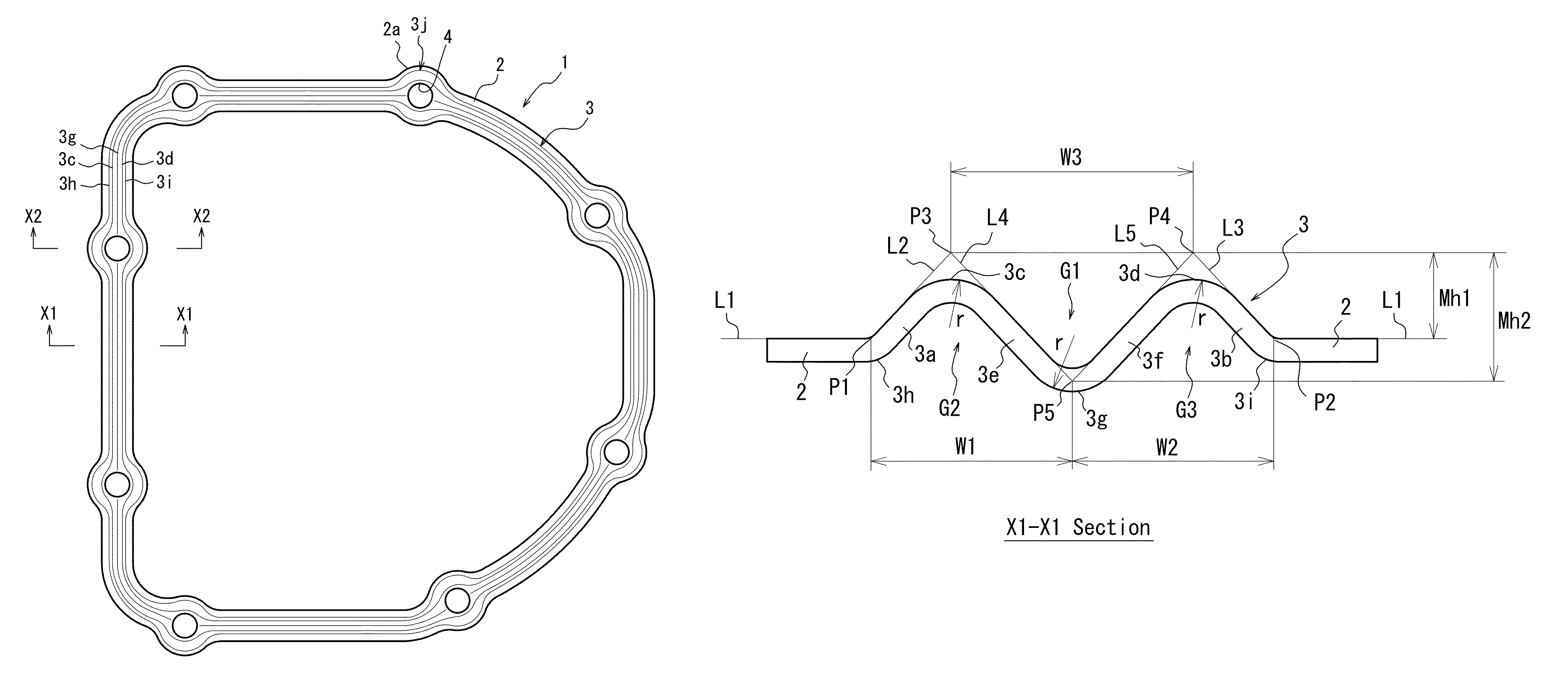
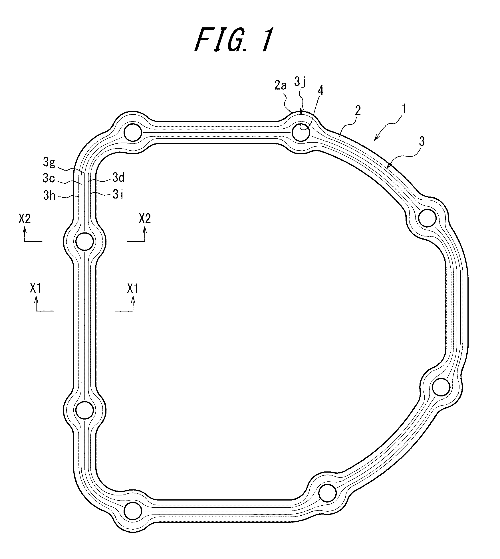
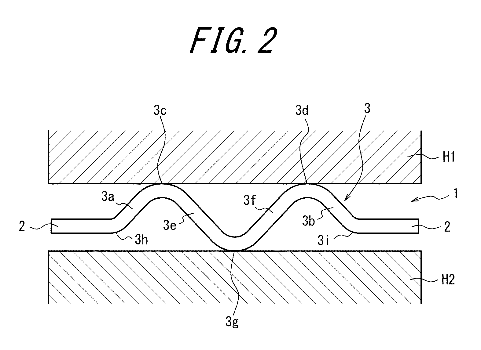
The present invention aims to provide a metal gasket that can better seal against blowholes on joint surfaces of housings while being less susceptible to lift-up or thrust phenomena. The metal gasket has an embossment portion placed on the base that consists of a pair of outer inclined portions and a pair of inner inclined portions connecting to each other at their tip ends. The embossment portions form multiple seal lines with respect to each of the housings, ensuring effective sealing even if a blowhole is present on the joint surface. A winding embossment portion can prevent malfunctions such as leakage of oil through the bolt hole while reducing the external diameter of the metal gasket.

Problems solved by technology

If such phenomena remain for a long time, the embossments lose their resilience to reduce the surface pressure of the seal lines and thus the sealing function against oil or the like is deteriorated.
Once the lift-up or thrust phenomenon occurs, the number of contact points decreases to impair the sealing function.
However, when the steel material is used, because of its lower resilience, it is concerned that the sealing function is reduced significantly by the lift-up phenomenon.
However, it is difficult to increase the surface pressure of all seal lines in the case where the steel material is used, so that it has been demanded to ensure a sufficient stability of the placed embossments against the thrust phenomenon.
Therefore, there is a risk that oil may flow over the seal lines.
However, the number of contact points may be reduced by the lift-up and thrust phenomena, so that it is still possible that oil or the like may leak.

Method used


Image

  • Metal gasket
  • Metal gasket
  • Metal gasket

Examples


examples

[0048]Inventors of the present invention have paid attention to the prior art of a metal gasket 300 as shown in FIG. 13 in order to verify the performance of the metal gasket configured as described above. In other words, in order to increase the surface pressure of the seal line at the tip end 3g, it is necessary to make the value of Mh2 larger than the value of Mh1 (i.e., to set the value of Mh2 / Mh1 to 1 or more). However, when the value of Mh2 / Mh1 is excessively large, there will be only a total of three seal lines formed as is the case with the metal gasket 300. In this connection, the inventors assumed that there might be a particularly preferred range for the relationship of Mh2 / Mh1, and experimentally made various metal gaskets with Mh1 being fixed to 0.21 mm, and Mh2 divided into 12 levels within a range of 0.13 mm-0.43 mm. All of the metal gaskets thus made were made of steel material, and satisfy the relationships of W3>W1 and W3>W2. The tip ends 3c, 3d, and 3g had an R-sh...


PUM


Abstract

There is provided a metal gasket that is less susceptible to lift and thrust phenomenon of housings and can effectively function as a sealing at a blowhole. The metal gasket includes an embossment portion provided with a pair of outer inclined portions and a pair of inner inclined portions. The metal gasket and satisfies the following relationships: Mh2 / Mh1=1.10−1.81, W3>W1, and W3>W2, where Mh1 and Mh2 are vertical lengths, and W1, W2 and W3 are horizontal lengths. When the gasket is sandwiched in between two housings, tip ends abut on the housing to form two seal lines, and root ends, and another tip end abut on the housing H2 to form three seal lines.

Description

CROSS REFERENCE TO RELATED APPLICATIONS[0001]The present application claims priority from pending Japanese Patent Application No. 2014-045469, filed Mar. 7, 2014, which is incorporated herein by reference.TECHNICAL FIELD[0002]The present invention relates to a metal gasket mounted between two housings accommodating a transmission or the like to prevent oil leakage. In particular, the present invention relates to a technology that ensures an effective sealing function of the metal gasket for a long time even under an occurrence of a lift-up phenomenon where a gap between the two housings becomes larger or a thrust phenomenon where housings move along the joint surfaces, or even if a blowhole exists on the joint surfaces.BACKGROUND ART[0003]A first housing accommodating a transmission combined with an internal combustion engine or the like, and a lid-shaped second housing are assembled together by bolts with a metal gasket being interposed therebetween. By tightening the bolts that fa...

Claims


Application Information

Patent Timeline
IPC IPC(8): F16J15/08F16H57/029
CPCF16H57/029F16J15/0887F16J15/0818
Inventor TOSA, OSAMUHIRAYAMA, SHINICHINAKAJIMA, KOICHISUZUKI, MASASHI
Owner NIPPON LEAKLESS IND CO LTD
Learn More