
Methods of additive manufacturing for glass structures

a technology of additive manufacturing and glass structure, which is applied in the direction of glass making apparatus, manufacturing tools, welding/soldering/cutting articles, etc., can solve the problems of unnecessarily complex equipment configuration of traditional am processes, glass and glass-ceramic materials introduce system complexity, and potential laser beam interference with the formed glass articles

Pending Publication Date: 2021-08-19
CORNING INC
View PDF0 Cites 0 Cited by
  • Summary
  • Abstract
  • Description
  • Claims
  • Application Information

AI Technical Summary

Benefits of technology

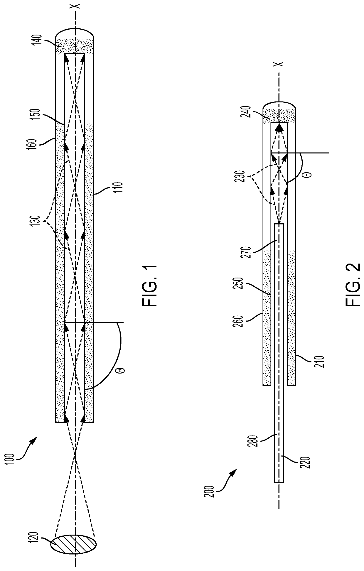
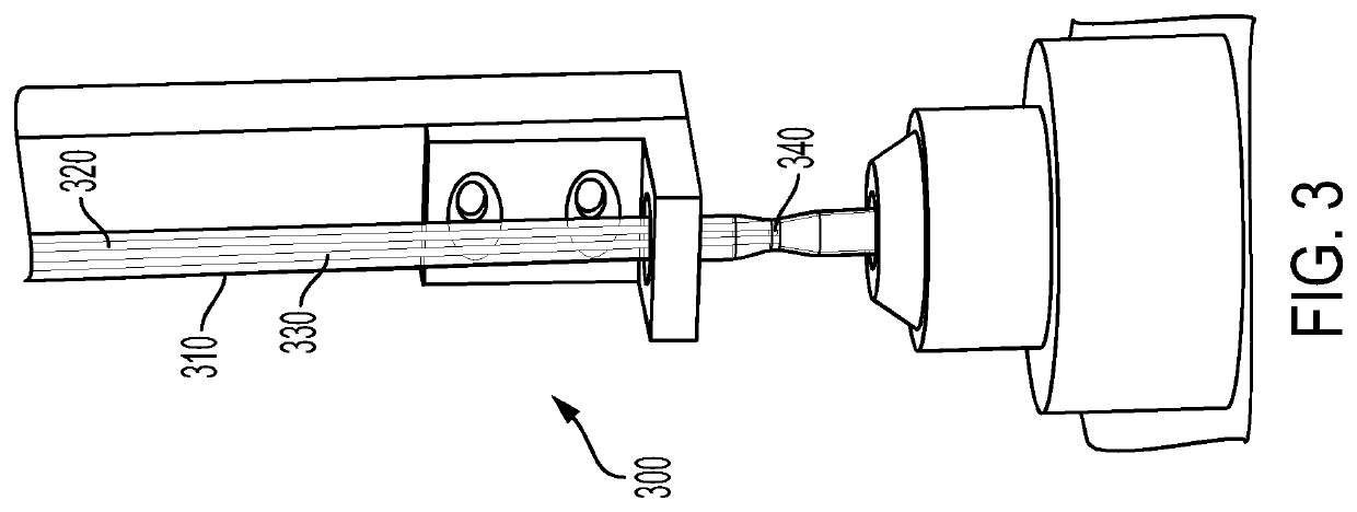
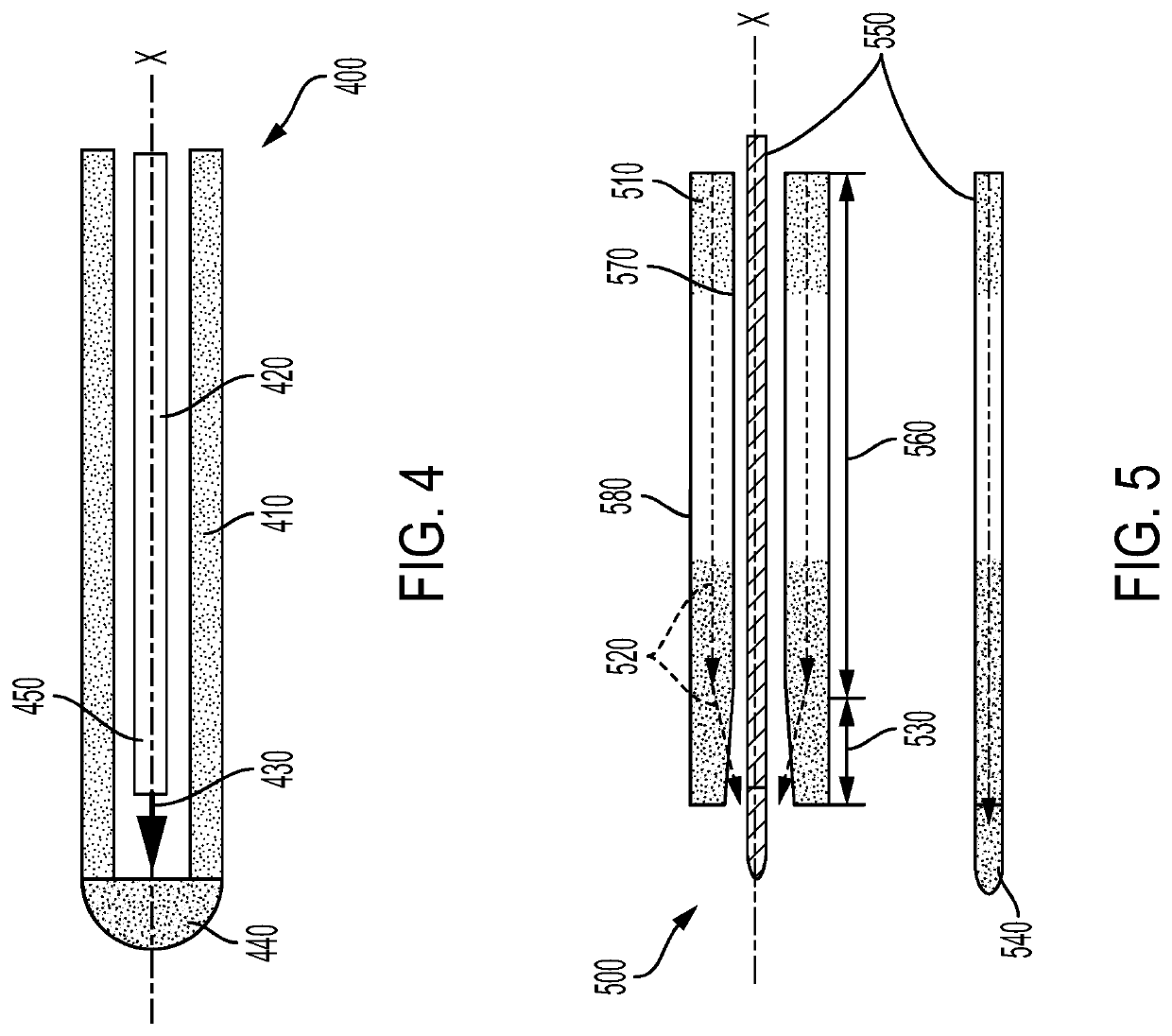
The patent describes a method for forming a structure by heating a glass or glass ceramic tubular structure using a laser beam. The laser beam is directed at the interior surface of the tubular structure and at least some of the laser beam is absorbed by the closed end region of the tubular structure. The laser beam can be directed at an angle greater than a predetermined incidence angle. The method can be used to create a two-dimensional shape or a three-dimensional shape. The glass or glass ceramic tubular structure has a high absorbance at the wavelength of the laser beam. The method can be performed using a hollow tube and a glass or polymer fiber. The technical effect of the patent is to provide a precise and efficient method for forming complex shapes in glass or glass ceramic tubular structures.

Problems solved by technology

Additive manufacturing of glass and glass ceramic materials have typically involved laser-based, binder-less approaches (e.g., glass-tubing, powder bed fusion, and blown-glass powder); however, traditional AM processes suffer from unnecessarily complex equipment configurations.
Thus, conventional AM processes for glass and glass-ceramic materials introduce system complexity and potential laser beam interference with the formed glass article.

Method used


Image

  • Methods of additive manufacturing for glass structures
  • Methods of additive manufacturing for glass structures
  • Methods of additive manufacturing for glass structures

Examples


Embodiment Construction

[0045]Reference will now be made in detail to exemplary embodiments which are illustrated in the accompanying drawings. Whenever possible, the same reference numerals will be used throughout the drawings to refer to the same or like parts. The components in the drawings are not necessarily to scale, emphasis instead being placed upon illustrating the principles of the exemplary embodiments. It should be understood that the present application is not limited to the details or methodology set forth in the description or illustrated in the figures. It should also be understood that the terminology is for the purpose of description only and should not be regarded as limiting. Additionally, any examples set forth in this specification are not limiting and merely set forth some of the many possible embodiments of the claimed invention.

[0046]Traditional laser-based, binder-less additive manufacturing methods of glass and glass ceramic articles have included glass-tubing, powder bed fusion,...


PUM

PropertyMeasurementUnit
incidence angleaaaaaaaaaa
wavelengthaaaaaaaaaa
inner diameteraaaaaaaaaa

Abstract

A method for forming a structure includes providing a glass or glass ceramic tubular structure (110) having an interior (150) and exterior surface (160) and at least a partially closed end region (140); heating the glass or glass ceramic tubular structure (110) to at least its softening point by: providing a laser beam; directing the laser beam (130) down the interior surface of the glass or glass ceramic tubular structure (110), at least some of the laser beam (130) directed at an angle greater than a predetermined incidence angle; and the laser beam (130) impinging on the closed end region (140) where at least some of the laser beam (130) is absorbed by the closed end region (140) of the glass or glass ceramic tubular structure; and moving at least one of: the glass or glass ceramic tubular structure or the end region relative to each other to form at least a two-dimensional shape from the glass or glass ceramic tubular structure.

Description

CROSS REFERENCE TO RELATED APPLICATIONS[0001]This application claims the benefit of priority of U.S. Provisional Application Ser. No. 62 / 686,316, filed on Jun. 18, 2018, the contents of which are relied upon and incorporated herein by reference in their entirety.FIELD[0002]The disclosure relates to additive manufacturing processes for inorganic materials.TECHNICAL BACKGROUND[0003]Additive manufacturing (AM) (also known as three dimensional (3D) printing or rapid prototyping) refers to processes where layers of material are formed under computer control to create three-dimensional objects by extrusion deposition, light polymerization, powder bed sintering, lamination, and metal wire deposition, for example. Conventional AM processes have often employed polymers, metals, and ceramics.[0004]Additive manufacturing of glass and glass ceramic materials have typically involved laser-based, binder-less approaches (e.g., glass-tubing, powder bed fusion, and blown-glass powder); however, trad...

Claims


Application Information

Patent Timeline
Patent Type & Authority Applications(United States)
IPC IPC(8): B23K26/34B23K26/06B23K26/067B29C64/295C03B19/02
CPCB23K26/34B23K26/0648B23K2103/54B29C64/295C03B19/02B23K26/067B33Y10/00
Inventor GALLAGHER, MICHAEL THOMASJARVIS, SCOTT MICHAELLI, XINGHUAWHEELER, NICHOLAS RYAN
Owner CORNING INC
Learn More