Projection lens and projection-type display apparatus using the lens

a projection lens and projection-type technology, applied in the field of projection lenses, can solve the problems of insufficient reduction of the size of the entire lens system and the length of the entire system, and achieve the effects of reducing the outer diameter of at least one reduction-side lens, preventing the length of the entire system, and reducing the outer diameter

Active Publication Date: 2011-10-06
FUJIFILM CORP
View PDF2 Cites 5 Cited by
  • Summary
  • Abstract
  • Description
  • Claims
  • Application Information

AI Technical Summary

Benefits of technology

[0041]The projection lens of the present invention and the projection-type display apparatus of the present invention using the projection lens satisfy the formula (1), as described. Therefore, it is possible to prevent the length of the entire system from becoming too long, while structuring the projection lens in such a manner that a ray separation optical system, a ray combination optical system, or the like is insertable in an area between the second lens group and the third lens group. The ray separation optical system separates illumination light and projection light from each other, and the ray combination optical system combines rays from plural modulation elements together. Specifically, in the projection lens of the present invention, a space for inserting an optical prism is provided between the second lens group and the third lens group in the lens system. Further, the projection lens of the present invention is structured so that a light valve is arrangeable without leaving a substantial space on the reduction side of the lens system. Therefore, it is possible to reduce the outer diameter of at least one reduction-side lens in the projection lens.
[0042]Further, since the projection lens of the present invention satisfies the formula (2), it is possible to reduce the outer diameter of at least one magnification-side lens in the projection lens, while the reduction side of the lens system is kept telecentric. In other words, when the formula (2) is satisfied, it is possible to limit the sum of the length of the first lens group and the length of the second lens group. Further, since the upper limit of d23 / f3 is defined by the formula (1), it is possible to reduce the length of the entire lens, and to reduce the size of the projection lens. Further, when the formula (2) is satisfied, length ff from the most-magnification-side surface in the entire system to the magnification-side focus position of the entire system is extremely short. Further, since the reduction side of the lens system is telecentric, a front-side focus position, at which rays condense most, is located in the vicinity of a magnification-side lens. Therefore, it is possible to solve the problem in conventional techniques that the external diameter of the magnification-side lens should be reduced. Further, it is possible to reduce the size of the entire lens system.

Problems solved by technology

However, the number of lenses is 10 or 11, which is many, and the total length is too long.
Therefore, the size of the entire lens system is not sufficiently reduced.

Method used


Image

  • Projection lens and projection-type display apparatus using the lens
  • Projection lens and projection-type display apparatus using the lens
  • Projection lens and projection-type display apparatus using the lens

Examples


example 1

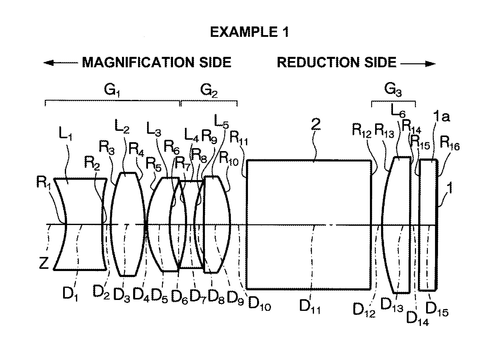
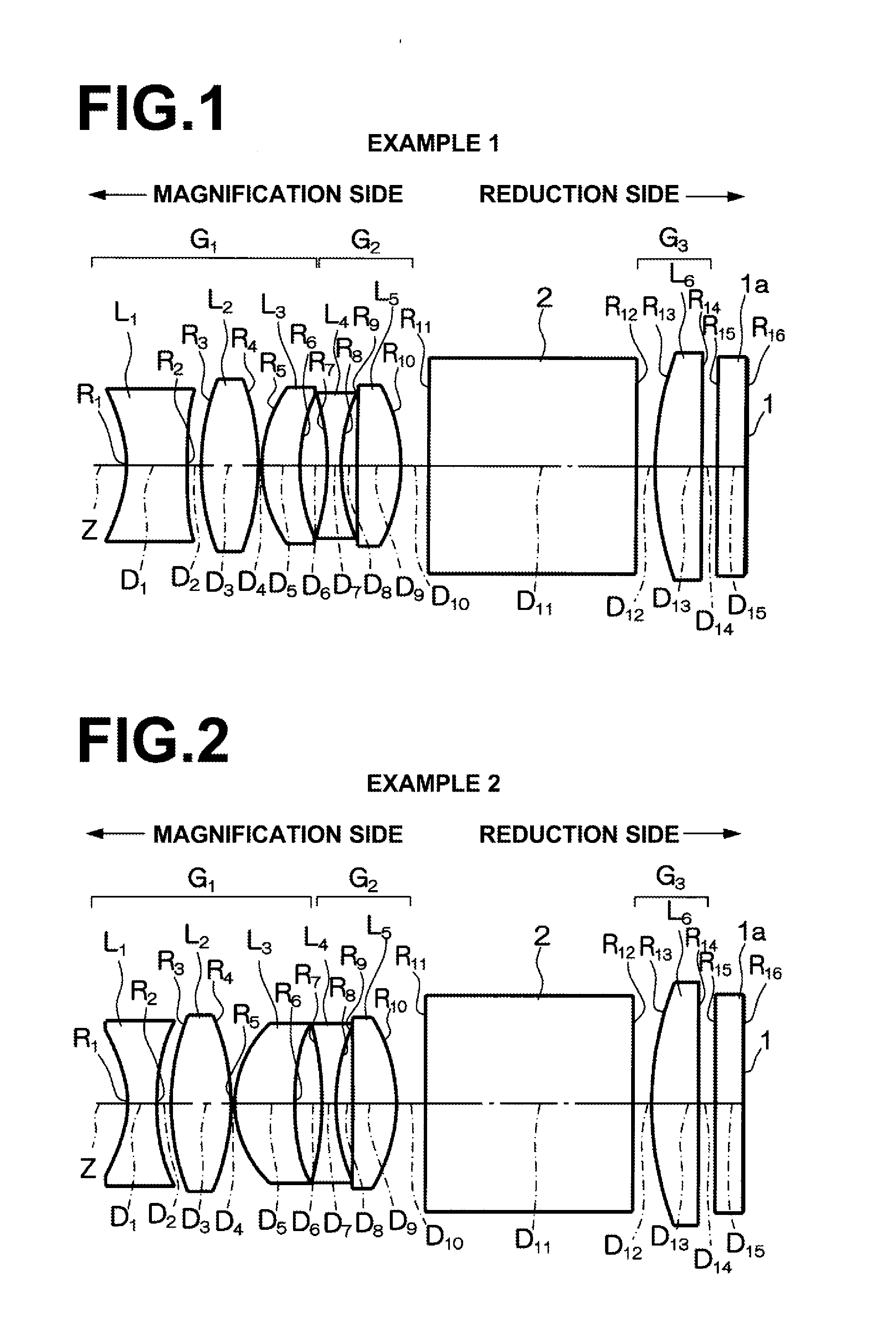
[0128]A projection lens in Example 1 is structured as illustrated in FIG. 1. Specifically, the projection lens is composed of first lens group G1, second lens group G2, and third lens group G3, which are sequentially arranged from the magnification side of the projection lens. The first lens group G1 is composed of first lens L1, second lens L2 and third lens L3, which are sequentially arranged from the magnification side. Both surfaces of the first lens L1 are aspheric (double concave (concave-concave) in the vicinity of the optical axis), and the first lens L1 is made of plastic. The second lens L2 is a double convex (convex-convex) lens made of glass. The third lens L3 is a positive meniscus lens having a convex surface facing the magnification side. The second lens group G2 is composed of fourth lens L4 and fifth lens L5. The fourth lens L4 is a double concave lens, and the fifth lens L5 is a double convex lens. The third lens group G3 is composed of sixth lens L6, which is a pl...

example 2

[0137]FIG. 2 is a schematic diagram illustrating the structure of a projection lens in Example 2. The projection lens in Example 2 is structured in a substantially similar manner to Example 1. However, in the projection lens of Example 2, both surfaces of the third lens L3 in the first lens group G1 are aspheric, and the third lens L3 is made of plastic. Further, in the projection lens of Example 2, the fifth lens L5 in the second lens group G2 is a positive meniscus lens having a convex surface facing the reduction side of the projection lens.

[0138]Further, in the projection lens of Example 2, a wide space is maintained between the second lens group G2 and the third lens group G3, and a color combination prism (or a ray separation prism) 2 is arranged in the space between the second lens group G2 and the third lens group G3. The space between the second lens group G2 and the third lens group G3 is set so as to satisfy the range defined by the formula (1). Specifically, the value of...

example 3

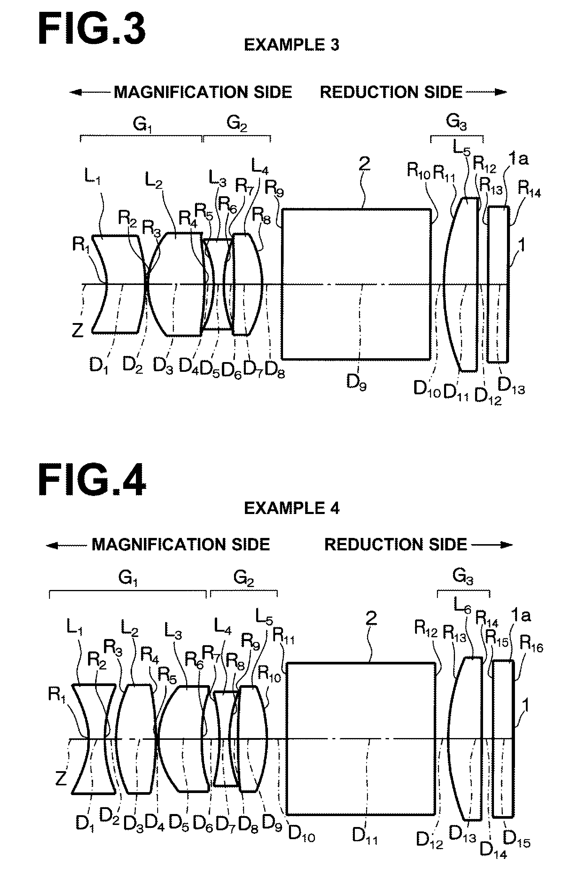
[0144]FIG. 3 is a schematic diagram illustrating the structure of a projection lens in Example 3. The projection lens in Example 3 is structured in a similar manner to Example 1. However, Example 3 greatly differs from Example 1 in that the projection lens of Example 3 is composed of five lenses. Specifically, the projection lens of Example 3 is composed of first lens group G1, second lens group G2 and third lens group G3, which are sequentially arranged from the magnification side. The first lens group G1 is composed of first lens L1 and second lens L2, which are sequentially arranged from the magnification side. Both surfaces of the first lens L1 are aspheric, and the first lens L1 is made of plastic (negative meniscus lens shape having a concave surface facing the magnification side in the vicinity of the optical axis). Both surfaces of the second lens L2 are aspheric, and the second lens L2 is made of plastic (double convex lens shape in the vicinity of the optical axis). Furthe...


PUM


Abstract

A projection lens is composed of a positive first lens group, a negative second lens group, and a positive third lens group, which are sequentially arranged from the magnification side of the projection lens, and the reduction side of the projection lens is telecentric. Further, the following formulas (1) and (2) are satisfied:
0.30≦d23/f3≦0.65  (1); and
10≦|D12/ff|  (2), where
    • d23: space in air between the second lens group and the third lens group,
    • f3: focal length of the third lens group,
    • D12: total length of the first lens group and the second lens group in the direction of an optical axis, and
    • ff: length from the most magnification-side surface in the entire system of the projection lens to a magnification-side focus position of the entire system.

Description

BACKGROUND OF THE INVENTION[0001]1. Field of the Invention[0002]The present invention relates to a projection lens to be mounted on a projection-type display apparatus, and the projection-type display apparatus. Particularly, the present invention relates to a projection lens appropriate for a small projector apparatus on which a light valve, such as a transmissive liquid crystal panel, a reflective liquid crystal panel and a DMD (digital micromirror device), is mounted, and to the projector apparatus.[0003]2. Description of the Related Art[0004]As projectors rapidly spread, and became widely used in recent years, a demand for small projectors that are light-weight and low-price, and which are conveniently usable and easily settable, increased. To satisfy such a demand, projections lenses for the projectors also need to be small, light-weight and low-price.[0005]When the back focus of a projection lens is reduced, it is possible to reduce the outer diameter of a reduction-side lens ...

Claims


Application Information

Patent Timeline
Patent Type & Authority Applications(United States)
IPC IPC(8): G02B9/24G02B9/14
CPCG02B13/04G02B13/22G02B13/16G02B9/14
Inventor YAMAMOTO, CHIKARA
Owner FUJIFILM CORP
Why Eureka
Try Eureka