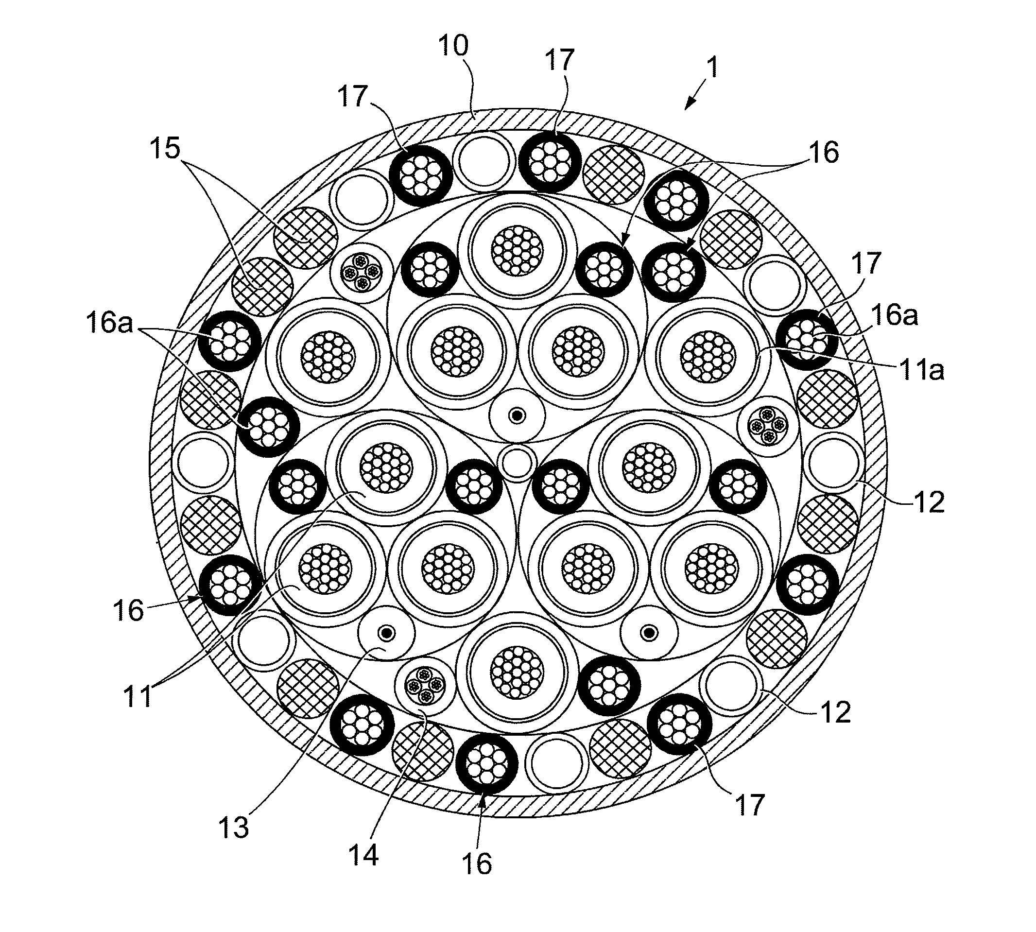
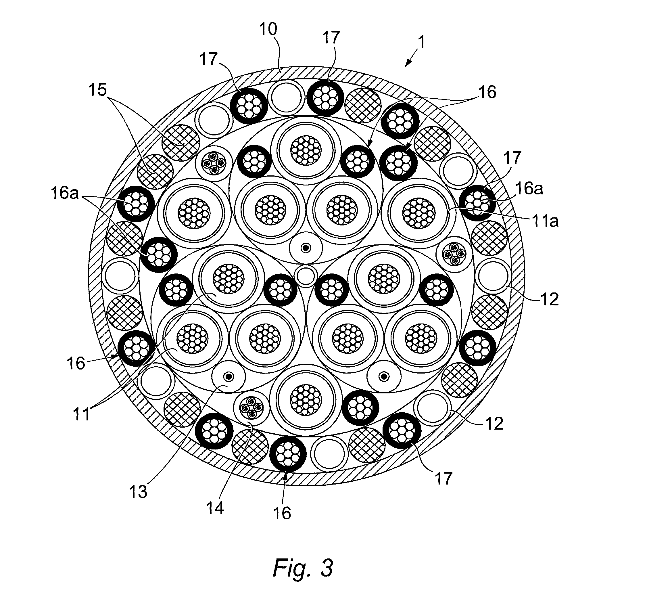
Umbilical

a technology of umbilical and stent, which is applied in the field of umbilical, can solve the problems of not solving the problem in considerable extended lengths, increasing the weight of the stent, so as to reduce the heat affected zone, reduce the risk of overheating the stent, and reduce the tube diameter

Inactive Publication Date: 2015-04-21
TECH FRANCE SA
View PDF23 Cites 5 Cited by
  • Summary
  • Abstract
  • Description
  • Claims
  • Application Information

AI Technical Summary

Benefits of technology

[0037]For example, in a first step, a metal strip is longitudinally folded around the rope in order to form a tube. There may be a small overlap at the junction between both sides of the folded strip. A second step consists in seam welding the folded strip at the junction / overlap area. The most suitable welding technique is laser welding (reduced heat affected zone, low risk of overheating the cable during the welding process).
[0038]A third possible step is reducing the tube diameter in order to compress the outer surface of the rope. This step may be carried out by a cold rolling process, where the tube is pulled through a series of suitably spaced and profiled rollers, or a cold drawing process, where the tube is drawn trough a die. The die reduction should be carefully chosen in order to achieve the suitable compressive effect without damaging or excessively elongating the rope. During this step, the external diameter of the rope is slightly reduced, thus achieving a good contact with the surrounding tube.

Problems solved by technology

As the water depth increases, the suspended weight also increases (for example in a riser configuration) until a limit is reached at which the umbilical is not able to support its own suspended weight.
However, due to the important specific gravity of steel, this solution now also adds a significant weight to the umbilical and does not solve the problem in considerable extended lengths.
However, in any dynamic conditions, this depth limit is naturally lower because of the fatigue phenomenon.
Furthermore, such steel reinforced umbilicals are very heavy and require evermore powerful and expensive installation vessels.
However, such umbilicals are difficult to manufacture and so are very expensive.

Method used


Image

  • Umbilical
  • Umbilical
  • Umbilical

Examples


Embodiment Construction

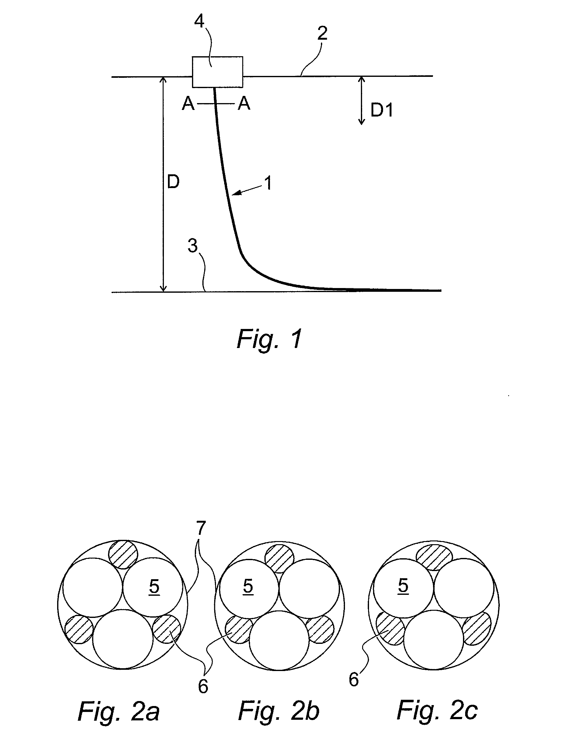
[0047]Referring to the drawings, FIG. 1 shows a schematic diagram of a first umbilical 1 in catenary configuration between a floating production unit 4 at a sea surface 2, or commonly at the ‘topside’, and a sea floor 3 or sea bed, with a depth D therebetween.

[0048]As is known in the art, the highest tensile and bending stresses are in the top section in the umbilical 1 as it approaches the floating production unit 4, shown in FIG. 1 by the section D1 of depth D. Traditionally, where the depth D is significant (such as >2000 m), load bearing members such as steel rods are provided along the whole length of the umbilical, generally to maintain ease of regular and constant manufacture.

[0049]However, whilst such load bearing members assist the tensile and bending stresses in the section D1, they become less useful, and therefor disadvantageous in terms of weight and cost, as the umbilical 1 continues towards the sea floor 3. The longer the umbilical, the greater the disadvantages are.

[...


PUM

PropertyMeasurementUnit
tensile strengthaaaaaaaaaa
depthaaaaaaaaaa
depthaaaaaaaaaa

Abstract

An umbilical for use in the offshore production of hydrocarbons, and in particular to a power umbilical for use in deep water applications is described, comprising a plurality of longitudinal strength members, wherein at least one longitudinal strength member comprises rope enclosed within a tube. In this way, the or each longitudinal strength member being a rope and tube combination achieves the synergistic benefit of favorable mechanical properties in the axial direction, with favorable mechanical properties in the radial direction during tensioning or the like of the umbilical, especially during installation.

Description

CROSS REFERENCE TO RELATED APPLICATIONS[0001]The present application is a 35 U.S.C. §371 National Phase conversion of PCT / GB2011 / 050740, filed Apr. 14, 2011, which claims benefit of British Application No. 1006460.8, filed Apr. 19, 2010, the disclosure of which is incorporated herein by reference. The PCT International Application was published in the English language.TECHNICAL FIELD OF THE INVENTION[0002]The present invention relates to an umbilical for use in the offshore production of hydrocarbons, and in particular to a power umbilical for use in deep water applications.BACKGROUND OF THE INVENTION[0003]An umbilical consists of a group of one or more types of elongated or longitudinal active umbilical elements, such as electrical cables, optical fibre cables, steel tubes and / or hoses, cabled together for flexibility, over-sheathed and, when applicable, armoured for mechanical strength. Umbilicals are typically used for transmitting power, signals and fluids (for example for fluid...

Claims


Application Information

Patent Timeline
Patent Type & Authority Patents(United States)
IPC IPC(8): E21B17/01H01B7/04
CPCH01B7/045Y10T29/49904
Inventor FOGG, DAVIDAN, XIAOXUEBROMFIELD, DAVEDOBSON, ALAN
Owner TECH FRANCE SA
Why Eureka
Try Eureka