Control of a brushless motor

a brushless motor and control technology, applied in the direction of single-phase motor control, electronic commutator, synchronous motor starter, etc., can solve the problem of excessive current level during timeout period, and achieve the effect of simple and cheap controller, simplified control, and simple and convenient control

Active Publication Date: 2015-09-01
DYSON TECH LTD
View PDF208 Cites 14 Cited by
  • Summary
  • Abstract
  • Description
  • Claims
  • Application Information

AI Technical Summary

Benefits of technology

[0005]The winding is therefore freewheeled when current exceeds a threshold or when the winding has been excited for a timeout period. The timeout period thus acts as a failsafe mechanism by limiting the maximum period of time over which the winding may be excited.
[0006]The rate at which current rises in the winding during excitation will depend on the magnitude of the voltage. Additionally, for a permanent-magnet motor, the rate at which current rises will depend on the speed of the motor; this is due to the back EMF induced in the winding by the rotor. By adjusting the timeout period in response to a change in one or both of the voltage and the motor speed, excessive currents may be avoided irrespective of changes in the voltage and / or motor speed.
[0009]The timeout period may be adjusted in response in a zero-crossing in the alternating voltage and a change in one of the RMS value of the alternating voltage and the motor speed. Accordingly, the timeout period is updated at regular intervals without the need for a dedicated timer. Moreover, by updating the timeout period in response to zero-crossings in the alternating voltage, control of the motor is relatively simple and thus a relatively simple and cheap controller may be used to implement the method.
[0011]The method may comprise repeatedly exciting and freewheeling the winding over each electrical half-cycle of the motor. This is particularly true during acceleration. The timeout period is then constant over each electrical half-cycle of the motor. This then simplifies the control. Where the winding is excited with a rectified voltage, the timeout period may be fixed over each half-cycle of the alternating voltage. The same timeout period is then used for each electrical half-cycle of the motor spanning one half-cycle of the alternating voltage. Again, this then simplifies the control and thus a relatively simple and cheap controller may be used to implement the method. The timeout period may then be updated at the start of the electrical half-cycle of the motor immediately following the zero-crossing in the alternating voltage.
[0012]The method may comprise storing a lookup table of control values. Adjusting the timeout period may then comprise indexing the lookup table using the voltage and / or the motor speed to select a control value, and using the control value to determine the timeout period. The use of a lookup table to determine the timeout period simplifies the control of the motor. Each control value may be an absolute value or a difference value. Where the control values are difference values, the method also comprises storing a reference value to which the difference value is applied to obtain the timeout period. Storing a difference value often requires less memory than an absolute value. As a result, the lookup table may be stored more efficiently.
[0015]The control system may comprise a rectifier for rectifying an alternating voltage and a zero-cross detector for detecting zero-crossings in the alternating voltage. The inverter then excites the winding with the rectified voltage in response to the first control signals, and the controller adjusts the timeout period in response to a zero-crossing detected by the zero-cross detector and a change in one of an RMS value of the alternating voltage and the motor speed. By employing a zero-cross detector, the controller is able to update the timeout period at regular intervals without the need for a dedicated timer.

Problems solved by technology

If a fixed timeout period were employed, it is possible that an excessive current level may be reached during the timeout period.

Method used


Image

  • Control of a brushless motor
  • Control of a brushless motor
  • Control of a brushless motor

Examples


specific example

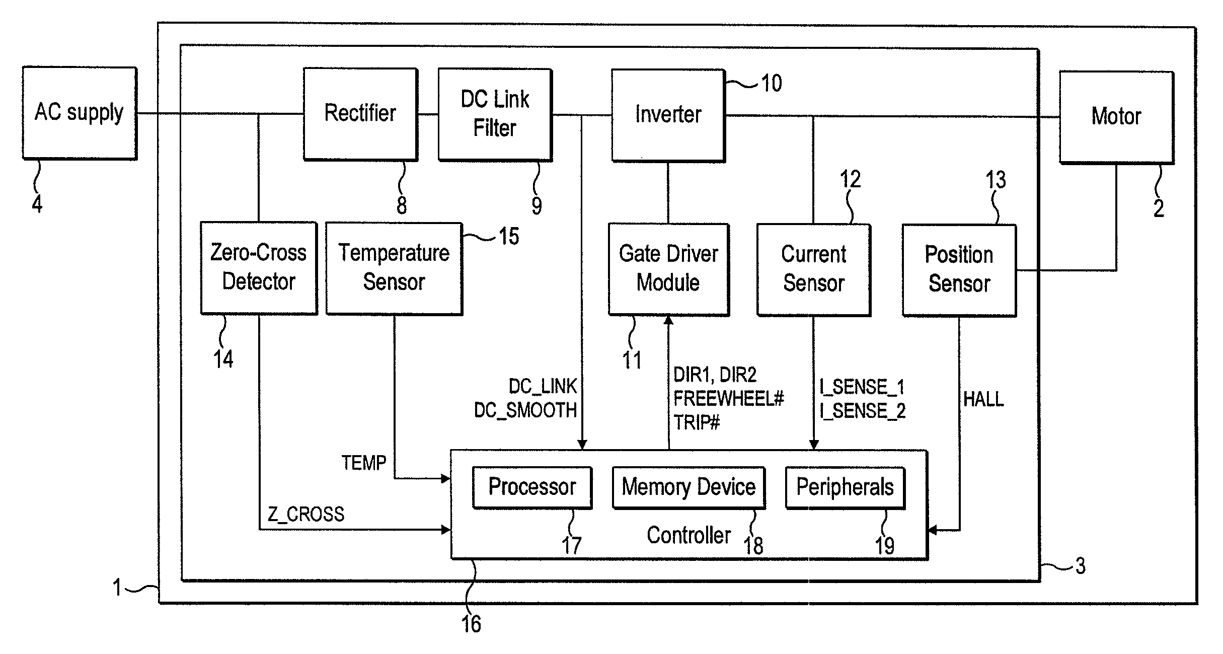
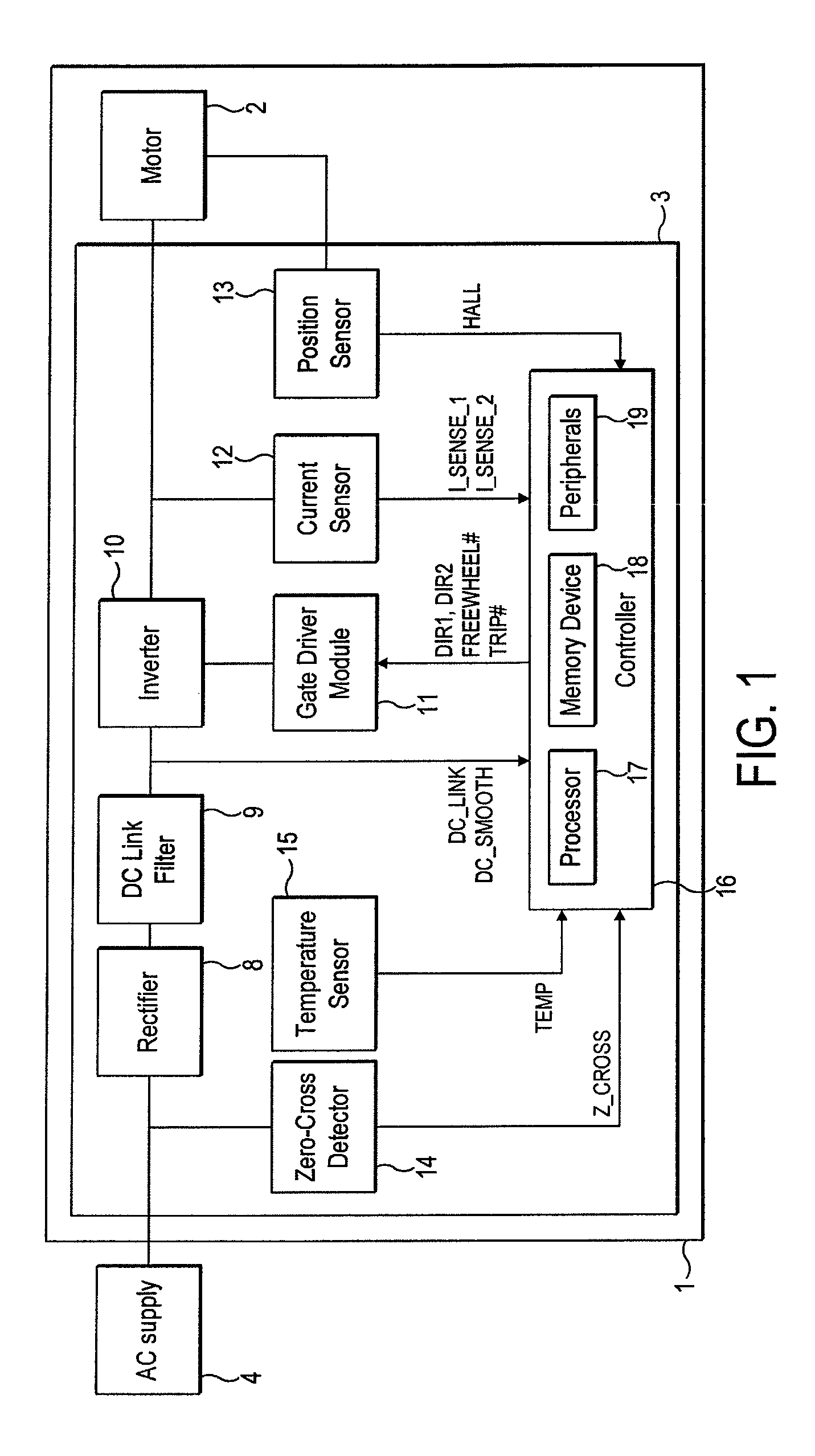
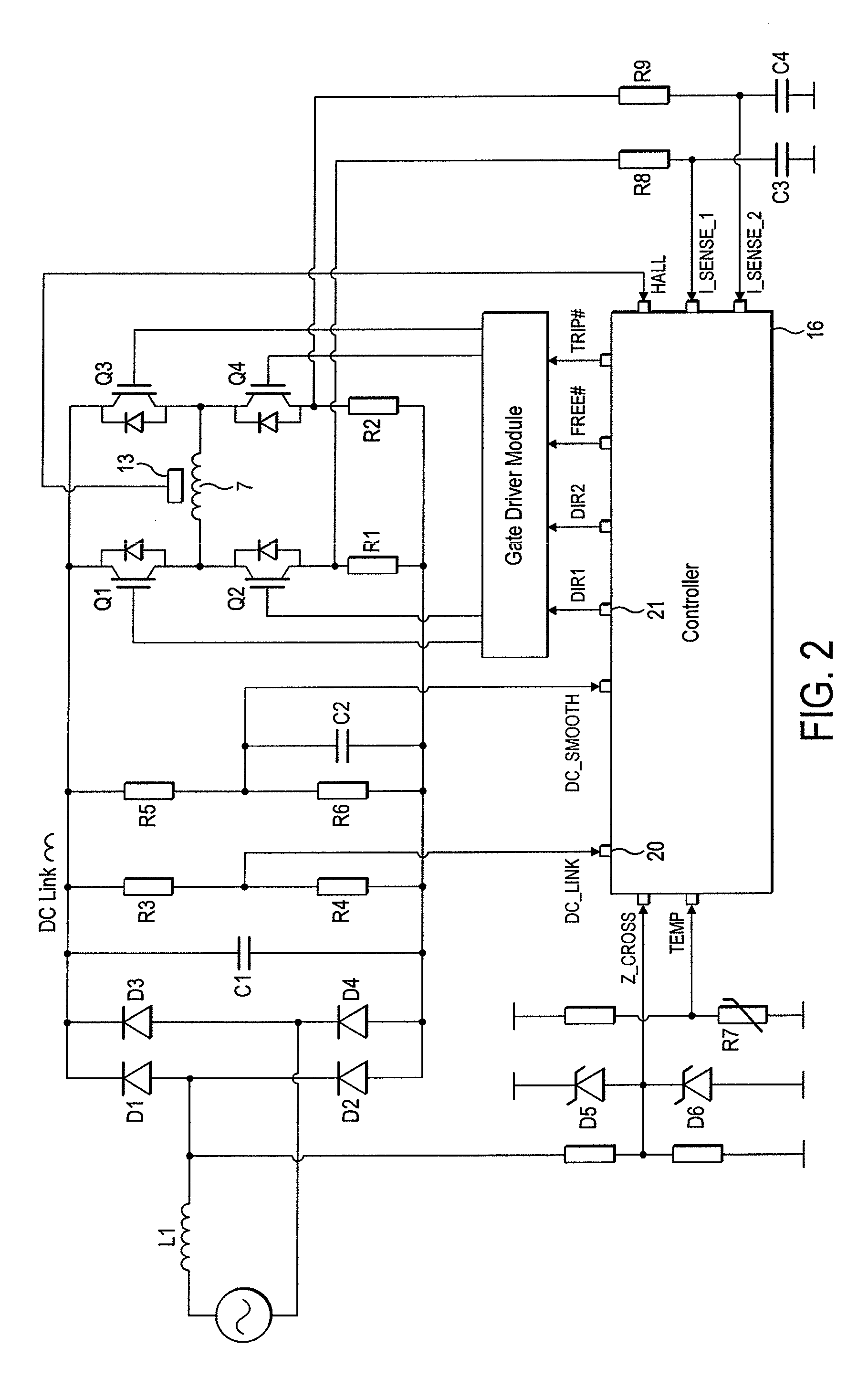
[0232]A particular embodiment of the motor system 1 will now be described by way of example only. Values for various hardware components of the motor system 1 are detailed in FIG. 19, while FIG. 20 lists various constants and thresholds employed by the controller 16. FIGS. 21 and 22 detail the flux-linkage characteristics of the link inductor L1 and the motor 2.

[0233]As illustrated in FIG. 23, the motor system 1 has seven modes of operation: Fault, Initialization, Stationary, Low-Speed Acceleration, Mid-Speed Acceleration, High-Speed Acceleration, and Running. Accordingly, in comparison to that previously described and illustrated in FIG. 8, the motor system 1 has one additional mode of operation.

[0234]Fault, Initialization, Stationary and Low-Speed Acceleration Modes are unchanged from that previously described. Mid-Speed Acceleration Mode corresponds to the previously-described High-Speed Acceleration Mode. Consequently, when operating in Mid-Speed Acceleration Mode, the controlle...


PUM


Abstract

A method of controlling a brushless motor that includes exciting a winding of the motor with a voltage, and freewheeling the winding when current in the winding exceeds a threshold or after the winding has been excited for a timeout period. The timeout period is adjusted in response to a change in one of the voltage and the motor speed. Additionally, a control system that implements the method, and a motor system that incorporates the control system.

Description

REFERENCE TO RELATED APPLICATIONS[0001]This application claims the priority of United Kingdom Application No. 1006398.0, filed Apr. 16, 2010, the entire contents of which are incorporated herein by reference.FIELD OF THE INVENTION[0002]The present invention relates to control of a brushless motor.BACKGROUND OF THE INVENTION[0003]A brushless motor generally includes a control system that controls the excitation of phase windings of the motor. The control system may employ a current control scheme in which a winding is excited until current in the winding exceeds a threshold. On exceeding the threshold, the control system freewheels the winding so as to allow current in the winding to decay. If, however, there is a fault in the control system, the control system may not detect that current in the winding has exceeded the threshold. The control system would then continue to excite the winding and the resulting excessive current may damage the control system and / or the motor.SUMMARY OF ...

Claims


Application Information

Patent Timeline
Patent Type & Authority Patents(United States)
IPC IPC(8): H03K5/00H02P6/00H02P29/02H02P6/18
CPCH02P6/002H02P6/181H02P29/028H02P2209/07H02P6/28H02P29/032H02P6/15H02P6/26H02P6/34H02P6/085
Inventor DAI, HANPING
Owner DYSON TECH LTD
Why Eureka
Try Eureka