Robotic guided endoscope

a robotic and endoscope technology, applied in the field of robotic guided endoscopes, can solve the problems of difficult intraoperative correction to reach the required operating site, difficult to achieve dexterity and precision of instrument control within the confines of a limited operating space, and difficulty in reducing the trauma of the operation, so as to reduce the trauma and the level of accuracy

Active Publication Date: 2015-09-08
MAZOR ROBOTICS
View PDF2 Cites 151 Cited by
  • Summary
  • Abstract
  • Description
  • Claims
  • Application Information

AI Technical Summary

Benefits of technology

[0008]The present disclosure describes new exemplary systems and methods for performing endoscopic surgical procedures with a level of accuracy which reduces the trauma which may be involved in the procedure. The system typically comprises a surgical robot whose position is fixed relative to the patient's bone, according to one implementation, by mounting the robot either directly or partially on a bone of the patient.
[0010]The method of mounting a miniature robot directly on the bone provides a convenient and compact implementation of this procedure, and is described in U.S. Pat. No. 6,837,892 for “Miniature Bone-attached Surgical Robot”. Other methods which involve attaching the robot to a bridge structure which is supported partly or wholly on bones of the patient are described in U.S. Pat. No. 7,887,567 for “Apparatus for Spinal Fixation of Vertebrae”, and a further support method is shown in co-pending PCT International Patent Application No. PCT / IL2012 / 000387 for “Active Bed Mount for Surgical Robot”. All of these methods completely or largely eliminate the effect of motion of the patient's bone during the operation.
[0013]Use of such a surgical robot enables the endoscope to be directed at the exact point desired, as determined by the surgeon. The surgeon, using preoperative images of the operation site, such as CT images, plans the exact entry position and the angular orientation of the endoscope port, such that it reaches the operation site without impacting with or even passing too close to any sensitive anatomical features in its entry path. During the operation itself, the robot can therefore be controlled to direct the endoscope cannula to its intended entry position and along in its intended path, using only two or sometimes somewhat more intra-operative fluoroscopic images to achieve correct registration of the robot to the preoperative CT images. By this means, the entire endoscopic procedure can be performed with minimal trauma to the patient's soft tissues, since the initial entry should accurately and safely position the endoscope so that the surgical tool is correctly positioned for the intended operation.

Problems solved by technology

However, it has been difficult to achieve dexterity and precision of instrument control within the confines of a limited operating space, further compounded by the need to operate from a 2D video image.
However, another area so far untackled is the need to provide accurate access for the endoscope to the operation site, in order to reduce the trauma of the procedure.
If an incision for an endoscopic procedure is made in the patient's soft tissue in the incorrect position or at an incorrect angle, it is difficult to make an intraoperative correction to reach the required operating site without either significantly enlarging the extent of the incision, or withdrawing and making a second incision to gain more accurate access to the operating site.
This problem is particularly acute for operations performed on the spine, such as percutaneous discectomy.

Method used


Image

  • Robotic guided endoscope
  • Robotic guided endoscope
  • Robotic guided endoscope

Examples


Embodiment Construction

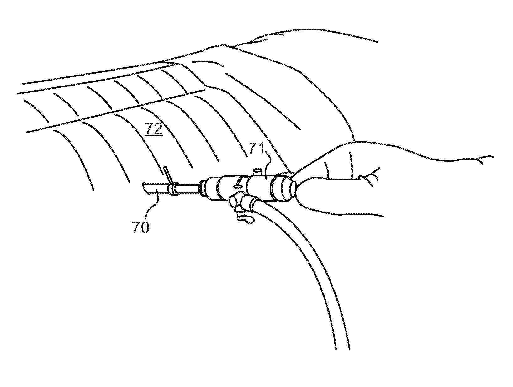
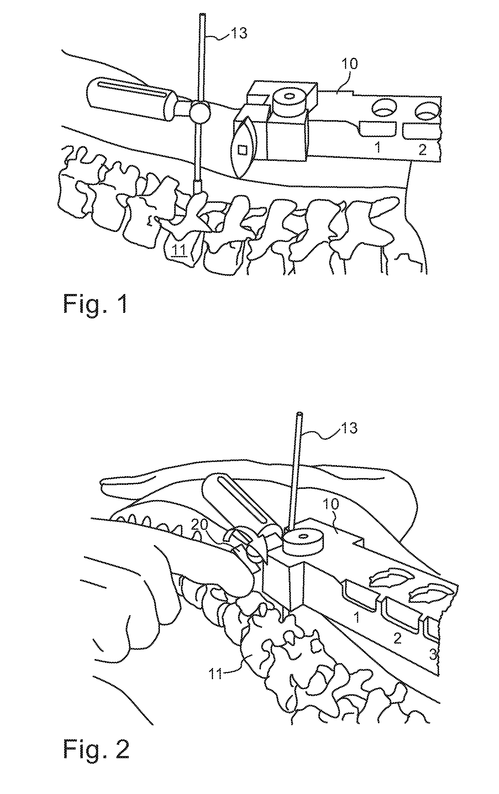
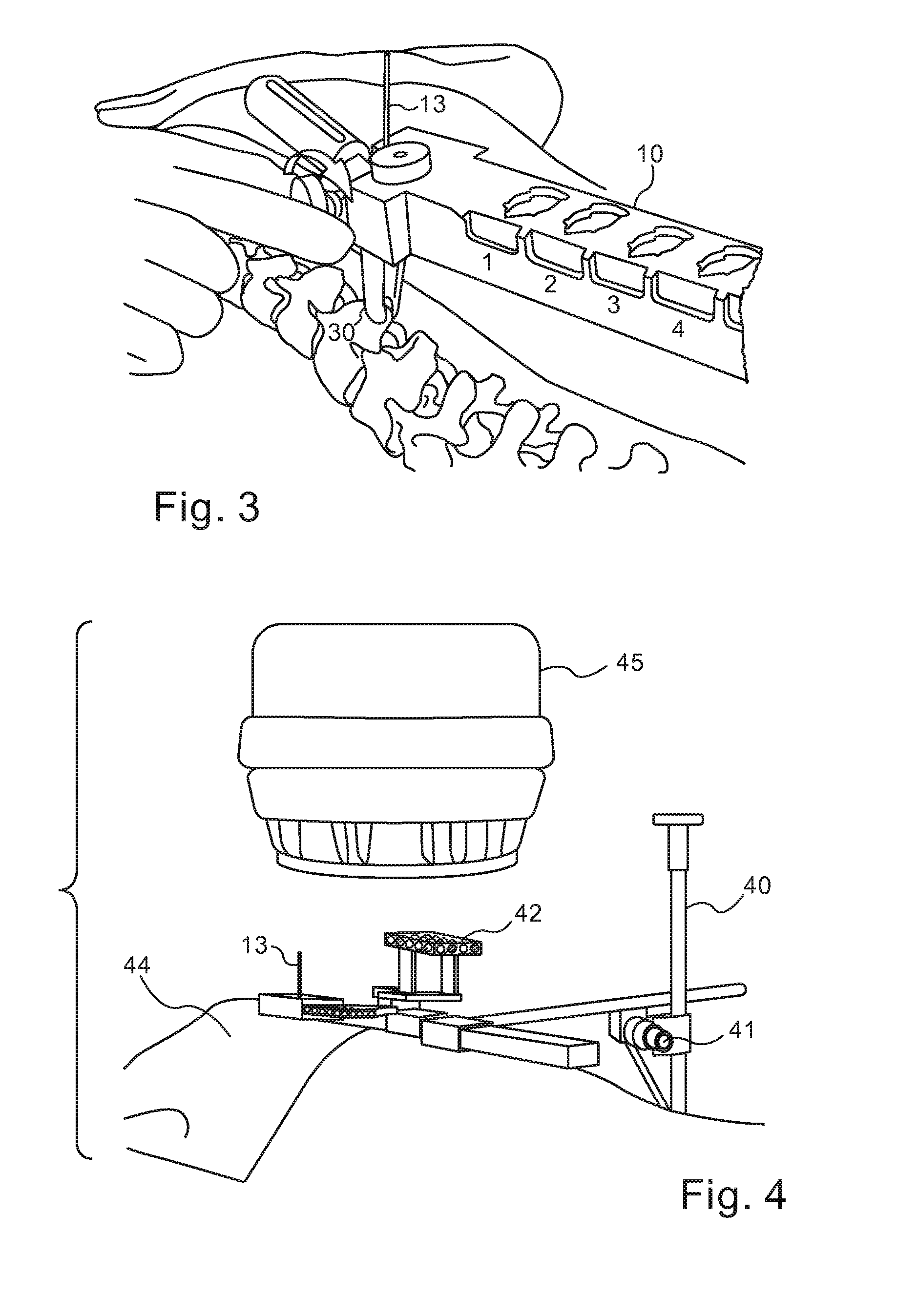
[0034]The following description is based on an exemplary spinal operation implementation in which the robot is mounted on a bridge element having a number of predetermined attachment positions for the robot. The bridge may be supported at one end on a vertebra of the patient and at the other end on a support post rigidly mounted to the bed (to be shown in FIG. 5). It is to be understood though that this is merely one exemplary procedure and method of supporting the robot, and the invention is not intended to be limited to spinal procedures or to this particular method. Reference is now made to FIG. 1, which illustrates schematically (on a phantom of the spine so that the exact subcutaneous procedure can be followed) how the bone supported end of the robotic bridge 10 can be fixed to one of the vertebrae 11 of the subject. A hole is drilled, preferably into the spinous process in the region of the operating site, and a supporting pin 13 is screwed in, by means of which the end of the...


PUM


Abstract

Systems and methods for performing robotic endoscopic surgical procedures, according to a surgical plan prepared on a preoperative set of three dimensional images. The system comprises a surgical robot whose coordinate system is related to that of fluoroscope images generated intraoperatively, by using a three dimensional target having radio-opaque markers, attached in a predetermined manner to the robot or to another element to which the robot is attached, such as the spinal bridge or an attachment clamp. The robot is mounted directly or indirectly on a bone of the patient, thereby nullifying movement of the bone, or a bone tracking system may be utilized. The coordinate system of the intraoperative fluoroscope images may be related to the preoperative images, by comparing anatomical features between both image sets. This system and method enables the endoscope to be directed by the robot along the exact planned path, as determined by the surgeon.

Description

CROSS-REFERENCE TO RELATED APPLICATIONS[0001]This application claims the benefit of priority from U.S. Provisional Patent Application No. 61 / 688,418, titled “Robotic Guided Endoscope,” and filed on May 14, 2012, the contents of which are incorporated herein by reference in their entirety.FIELD OF THE INVENTION[0002]The present invention relates to the field of robotically guided endoscopic procedures, especially for use in orthopedic procedures performed on the spine.BACKGROUND OF THE INVENTION[0003]Endoscopes are a prime element used in order to achieve Minimally Invasive Surgery (MIS). However, it has been difficult to achieve dexterity and precision of instrument control within the confines of a limited operating space, further compounded by the need to operate from a 2D video image. The application of robotic technology has the potential to contribute significantly to the advancement of endoscopic spine surgery.[0004]As described in the section on “Robotics: An Approach to Minim...

Claims


Application Information

Patent Timeline
Patent Type & Authority Patents(United States)
IPC IPC(8): A61B1/00A61B6/12A61B19/00A61B6/00G01R33/28A61B6/03A61B8/08A61B17/00
CPCA61B1/00154A61B6/12A61B6/485A61B6/487A61B6/5247A61B19/2203G01R33/285A61B6/032A61B8/0841A61B19/201A61B2017/00261A61B2019/5295A61B2019/5466A61B2019/5483A61B34/30A61B90/11A61B2090/367A61B2090/3966A61B2090/3983
Inventor ZEHAVI, ELISHOHAM, MOSHE
Owner MAZOR ROBOTICS
Why Eureka
Try Eureka